Capillary tube/plate refrigerant/air heat exchanger for use in conjunction with a method and apparatus for inhibiting ice accumulation in HVAC systems

a technology of ice accumulation and refrigerant, which is applied in the direction of defrosting, domestic cooling apparatus, etc., can solve the problems of system inability to acquire sufficient heat from the air to operate at design levels, shorten compressor life, and excessive wear, so as to reduce system operational design efficiency

Inactive Publication Date: 2006-04-27
EARTH TO AIR SYST
View PDF17 Cites 13 Cited by
  • Summary
  • Abstract
  • Description
  • Claims
  • Application Information

AI Technical Summary

Benefits of technology

[0012] It is an object of the invention to provide an alternative, and potentially better, example of a refrigerant / air heat exchanger means / design which could alternatively be utilized to inhibit ice accumulations on system component areas of any refrigerant-based heat transfer system or evaporative cooling system where accumulated frozen moisture, such as frozen humidity, frozen rain, snow, or hail, would decrease system operational design efficiencies for any reason.

Problems solved by technology

However, when typical air-source heat pump systems are operating in the heating mode, since the refrigerant fluid, which is being circulated into the exterior outdoor heat exchange unit exposed to the air, is typically below the freezing point of water, as the exterior air temperature approaches, or falls below, the freezing point of water, humidity in the air collects on the finned tubing and is frozen.
This freezing humidity gradually builds up ice accumulations to the extent that it blocks the airflow designed to pass over the finned tubing, thereby rendering the system unable to acquire sufficient heat from the air to operate at design levels.
This periodic defrost cycle results in excessive wear and tear on the compressor, tending to shorten compressor life, as well as in lowered system efficiencies and higher operational costs.
Similarly, in large commercial evaporative cooling chillers, which must periodically operate in below freezing temperatures, and which sometimes must operate with a cooling load significantly less than called for by system design, the water utilized for evaporative cooling on the exterior of the heat transfer tubing may freeze.

Method used


Image

  • Capillary tube/plate refrigerant/air heat exchanger for use in conjunction with a method and apparatus for inhibiting ice accumulation in HVAC systems
  • Capillary tube/plate refrigerant/air heat exchanger for use in conjunction with a method and apparatus for inhibiting ice accumulation in HVAC systems
  • Capillary tube/plate refrigerant/air heat exchanger for use in conjunction with a method and apparatus for inhibiting ice accumulation in HVAC systems

Examples


Embodiment Construction

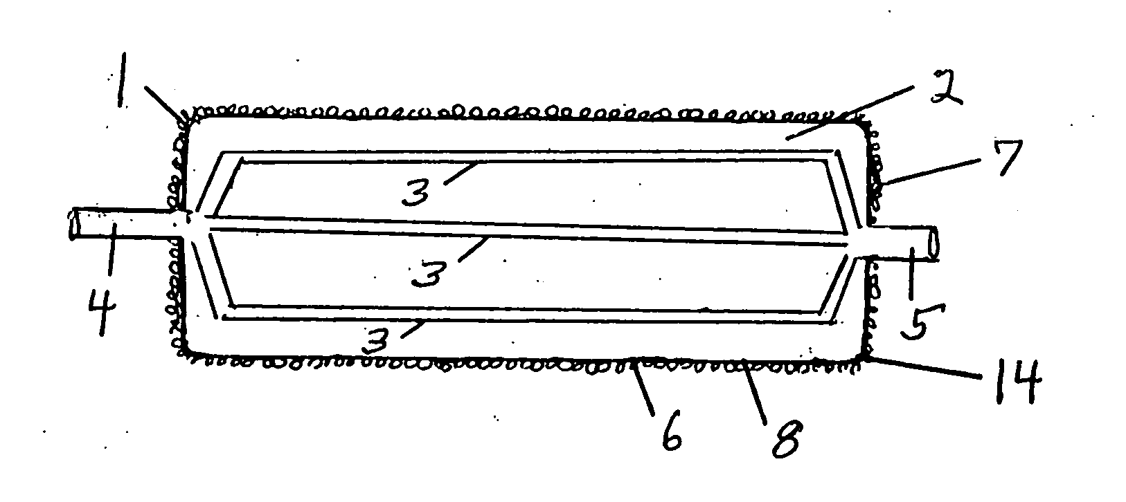
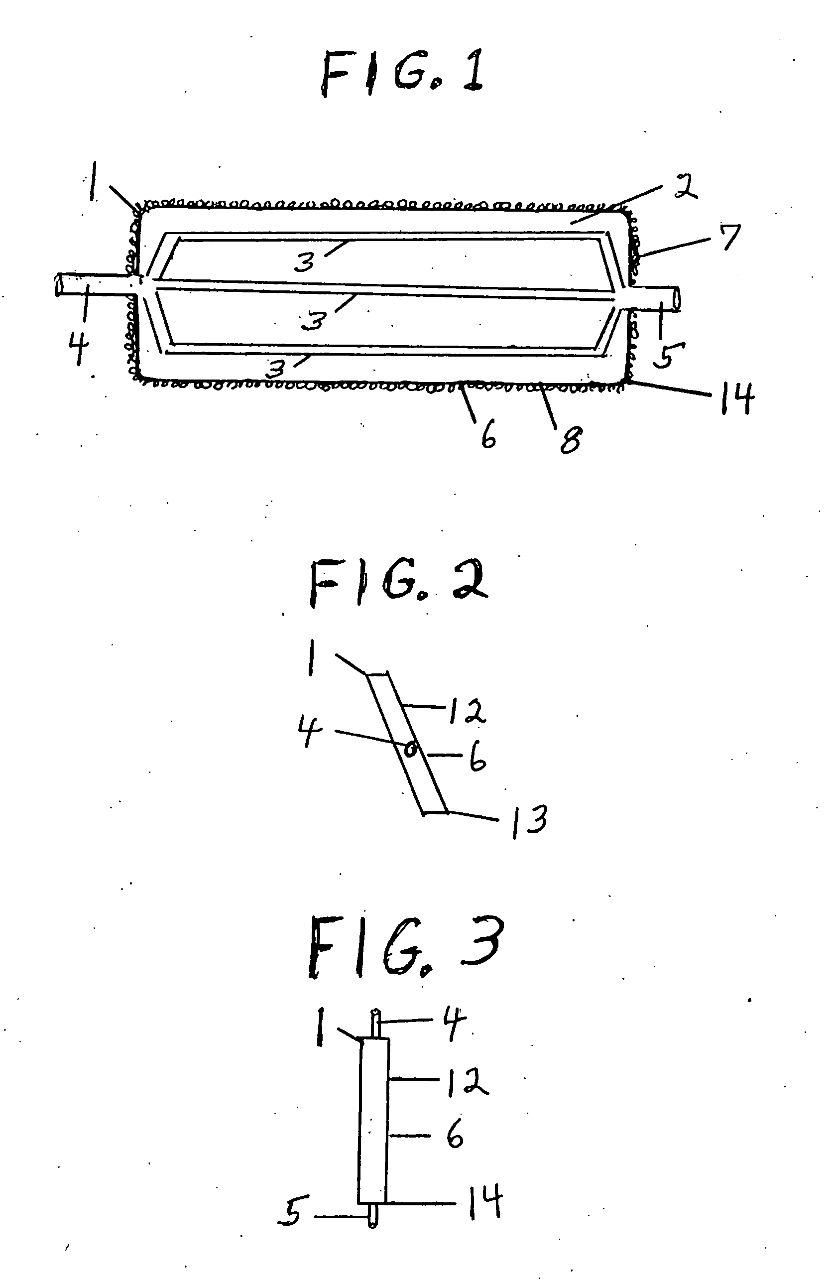
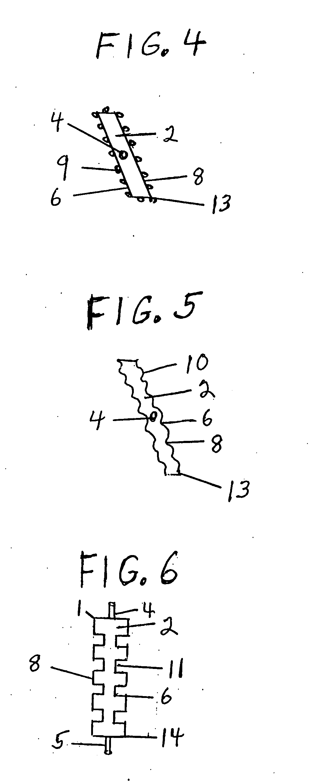
[0026] A method and apparatus for inhibiting condensation ice accumulation on heat transfer systems, including refrigerant-based heating and cooling systems, and on an evaporative cooling system, according to the invention, utilizes a non-stick coating applied to capillary tube / plate means / design heat exchange components where ice accumulation is not desirable because such ice decreases overall system operational efficiencies.

[0027] The following detailed description is of the best presently contemplated mode of carrying out the invention. The description is not intended in a limiting sense, and is made solely for the purpose of illustrating the general principles of the invention. The various features and advantages of the present invention may be more readily understood with reference to the following detailed description taken in conjunction with the accompanying drawings.

[0028] Referring now to the drawings in detail, where like numerals refer to like parts or elements, there ...


PUM

PropertyMeasurementUnit
thicknessaaaaaaaaaa
heat conductiveaaaaaaaaaa
gravityaaaaaaaaaa

Abstract

A non-stick coating, which inhibits frozen moisture accumulation, is applied to the exterior exposed portions of a refrigerant/air heat exchanger, which heat exchanger is comprised of a capillary tube/plate means/design, which plate has an exterior surface that is comprised of at least one of raised dots, ridges, trenches, and a flat surface, which means/design facilitates the shedding of frozen moisture and maximizes heat exchanger surface area exposure to the air; for use in conjunction with an air source heat pump system, an evaporative cooling system or a chiller, or as a supplement to a water-source heat pump system or to a direct expansion heat pump system; and for use with any other refrigerant-based heating system or cooling system.

Description

CROSS-REFERENCES TO RELATED APPLICATIONS [0001] This application is a Continuation-In-Part application which claims benefit of co-pending U.S. patent application Ser. No. 10 / 073,515 filed Feb. 11, 2002, entitled “Method and Apparatus for Inhibiting Ice Accumulation in HVAC Systems” which is hereby incorporated by reference.[0002] A portion of the disclosure of this patent document contains material that is subject to copyright protection. The copyright owner has no objection to the facsimile reproduction by anyone of the patent document or the patent disclosure, as it appears in the U.S. Patent and Trademark Office patent file or records, but otherwise reserves all copyright rights whatsoever. STATEMENT REGARDING FEDERALLY SPONSORED RESEARCH OR DEVELOPMENT [0003] Not Applicable REFERENCE TO SEQUENCE LISTING OR COMPUTER PROGRAM LISTING APPENDIX [0004] Not Applicable BACKGROUND OF THE INVENTION [0005] This invention relates to the field of refrigerant-based heating and cooling systems...

Claims


Application Information

Patent Timeline
Patent Type & Authority Applications(United States)
IPC IPC(8): F28F13/18F25D21/00F25B39/02F25D21/04F28F19/00
CPCF25D21/04F28F13/182F28F19/006
Inventor WIGGS, B. RYLAND
Owner EARTH TO AIR SYST
Why Eureka
Try Eureka