Web cleaner

a cleaning and web technology, applied in the field of cleaning webs, can solve the problems of shortening the useful life of the cleaning process, reducing the quality of the resultant printing, and time-consuming and expensiv

Inactive Publication Date: 2006-04-27
PDM
View PDF8 Cites 22 Cited by
  • Summary
  • Abstract
  • Description
  • Claims
  • Application Information

AI Technical Summary

Benefits of technology

[0054] a shutter moveable, in the absence of the web, from an open position to a closed position, in which closed position the shutter is located between the respective

Problems solved by technology

The surface of the paper may carry dust and dirt particles, lint, loose paper fibres and loose paper coating particles which can all be transferred to the printing apparatus itself where they accumulate and degrade the quality of the resul

Method used


Image

  • Web cleaner
  • Web cleaner
  • Web cleaner

Examples


Embodiment Construction

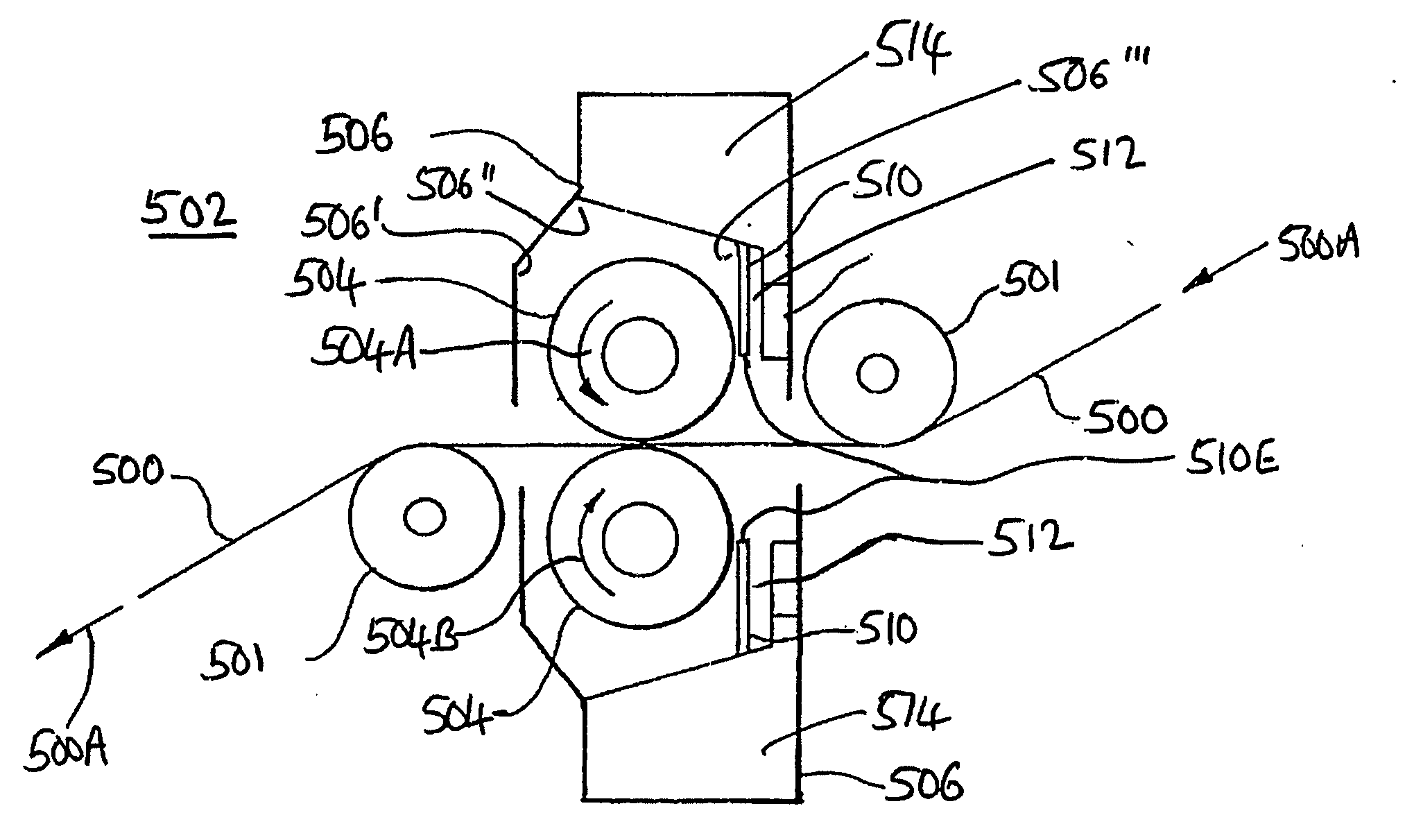
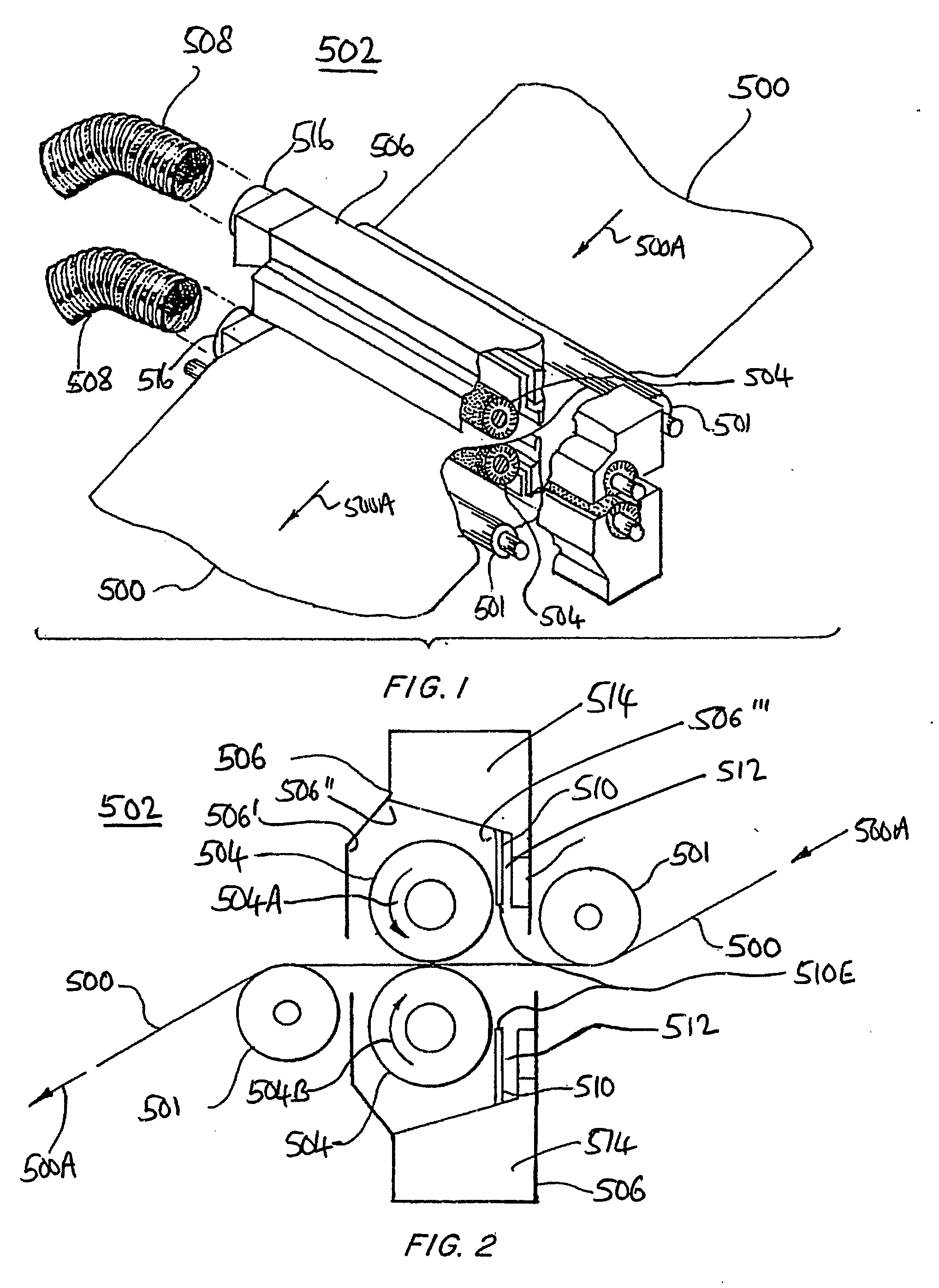
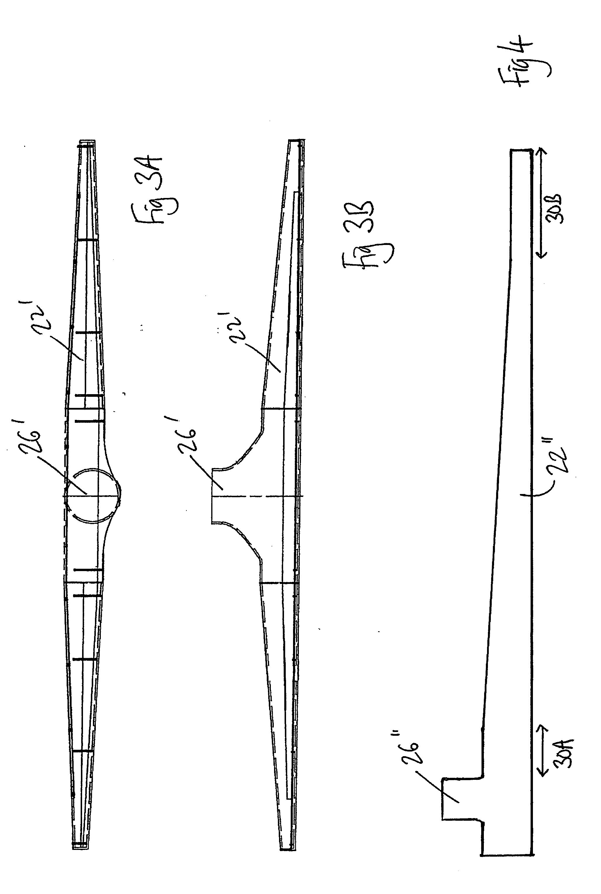
[0106] Referring now in particular to FIGS. 1 to 4, the prior art apparatus 502 of FIGS. 1 and 2 has a vacuum chamber housing 506 of uniform shape with respect to the whole length of the roller 504. In other words, the lateral cross-section (with respect to the axis of rotation of the roller 504) has the same shape at whichever point the cross-section is taken. The outlet 516, to which the vacuum pump is connected via ducts 508, is arranged at the end of chamber 514 defined in housing 506. The inventor has appreciated that this has the important consequence of providing a non-uniform pressure with respect to the axial length of the roller 504. That is, the pressure is least (degree of vacuum is greatest) at the end of the chamber 514 nearest the outlet 516. Thus, the vacuum applied must be relatively greater so that the actual vacuum achieved at the end of the roller 504 distant from the outlet 516 is sufficient (which carries the danger that the degree of vacuum at the end of the r...


PUM


Abstract

The invention is relates a web cleaning apparatus including: a pair of operatively rotating cleaning rollers operatively disposed on opposite sides of the web; a housing surrounding a major part of the surface of each roller; a vacuum chamber substantially co-extensive with each roller; a longitudinal slot extending parallel to each roller and substantially co-extensive therewith, the slot having an inlet proximate the roller surface and an outlet in communication with the vacuum chamber and operatively providing an air flow path from adjacent the roller into the vacuum chamber, wherein the air flow speed at each inlet is not less than the surface speed of the rollers, and a method of using such apparatus. Another apparatus of the invention includes a housing surrounding the roller and spaced therefrom with a gap of about 0.5 mm to about 5 mm. Further embodiments of the invention provide a shutter for controlling the air flow around the rollers in a cleaning step. Further embodiments of the invention provide a valve controlled bypass line whereby a given portion of a web cleaning apparatus can communicate with the atmosphere such that it is not under vacuum.

Description

BENEFIT CLAIMS [0001] This application claims the benefit of British Application No. GB 0423467.0, filed 22 Oct. 2004. FIELD OF THE INVENTION [0002] The present invention relates to apparatus and methods for cleaning moving webs of material, and in particular for cleaning webs of printable material, in particular paper, prior to printing in a printing press such as a lithographic, flexographic or gravure printing press or the like. BACKGROUND OF THE INVENTION [0003] The requirement for cleaning webs of printing substrate (paper) is well known in the art. The surface of the paper may carry dust and dirt particles, lint, loose paper fibres and loose paper coating particles which can all be transferred to the printing apparatus itself where they accumulate and degrade the quality of the resultant printing. This necessitates cleaning of the printing apparatus on a frequent basis which is time consuming and expensive. The cleaning process itself for printing plates, blankets and associat...

Claims


Application Information

Patent Timeline
IPC IPC(8): B41F35/00B08B1/02B08B5/02B08B5/04B08B15/04B41F23/00
CPCB08B1/02B08B5/026B08B5/046B08B15/04B41F23/002A47L5/38B08B5/04B41F23/00G01L7/00
Inventor BENNET, LESLIE
Owner PDM
Why Eureka
Try Eureka