Steering device
a steering device and axial installation technology, applied in mechanical devices, couplings, transportation and packaging, etc., can solve the problems of affecting the service life of the axial installation device, so as to reduce the manufacturing cost of the parts and eliminate the effect of backlash
- Summary
- Abstract
- Description
- Claims
- Application Information
AI Technical Summary
Benefits of technology
Problems solved by technology
Method used
Image

Examples
first embodiment
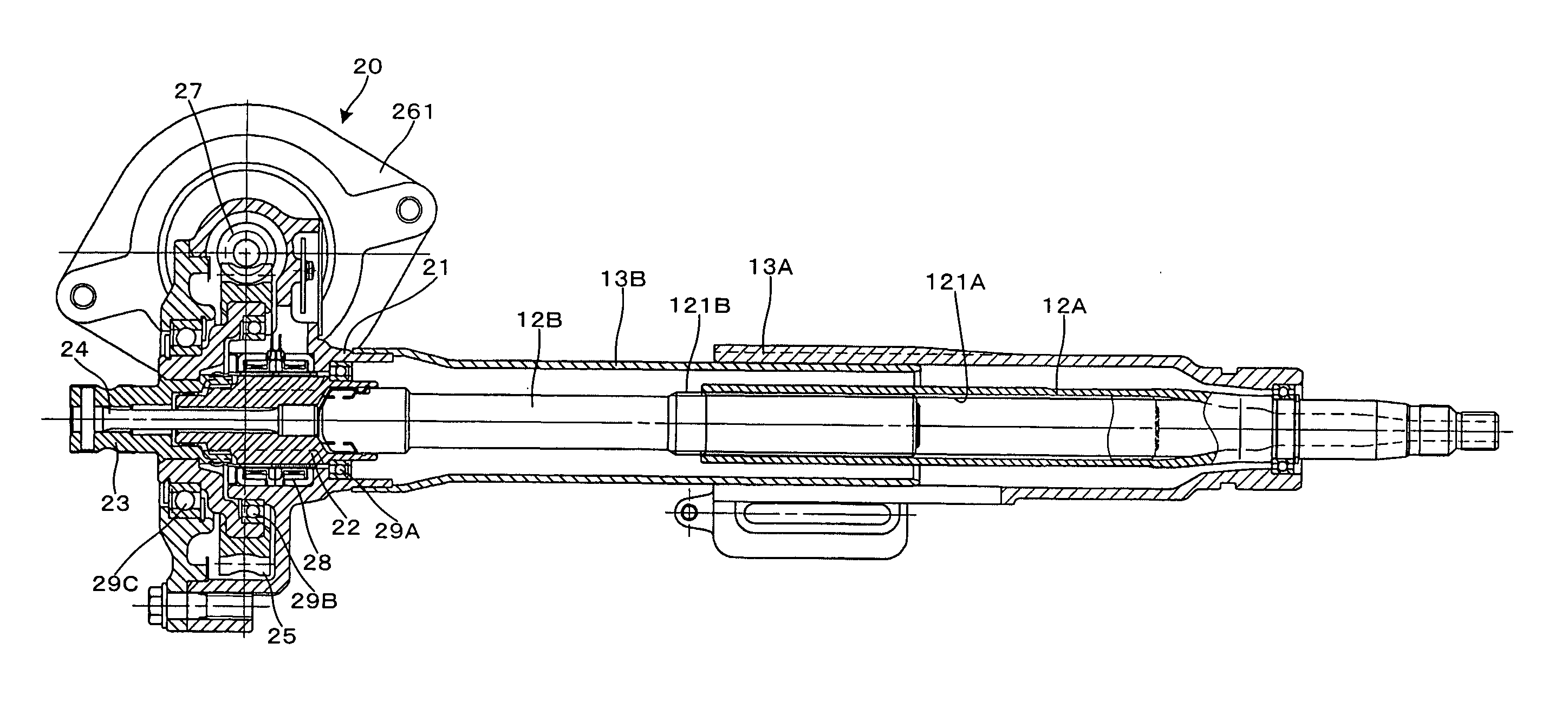
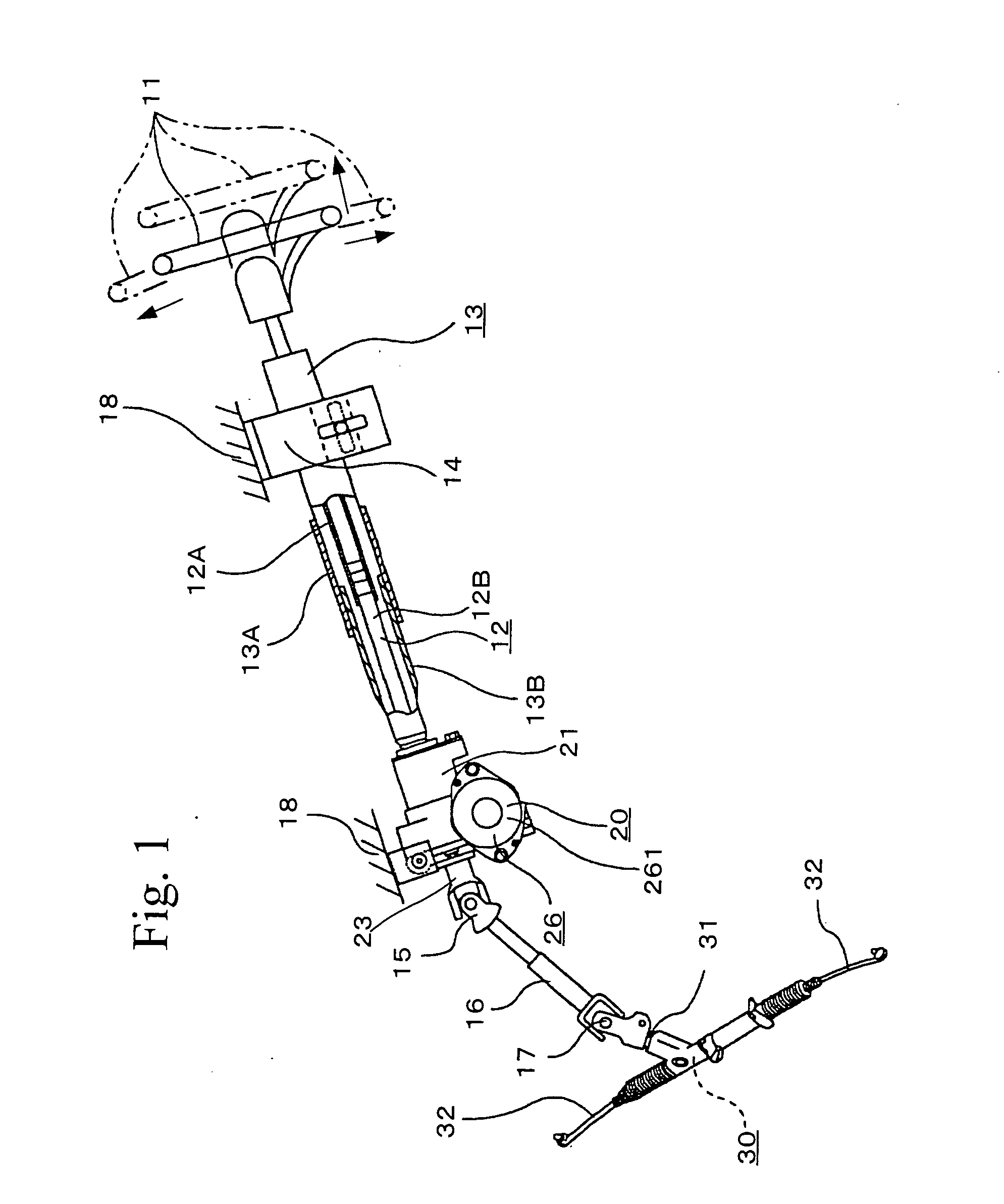
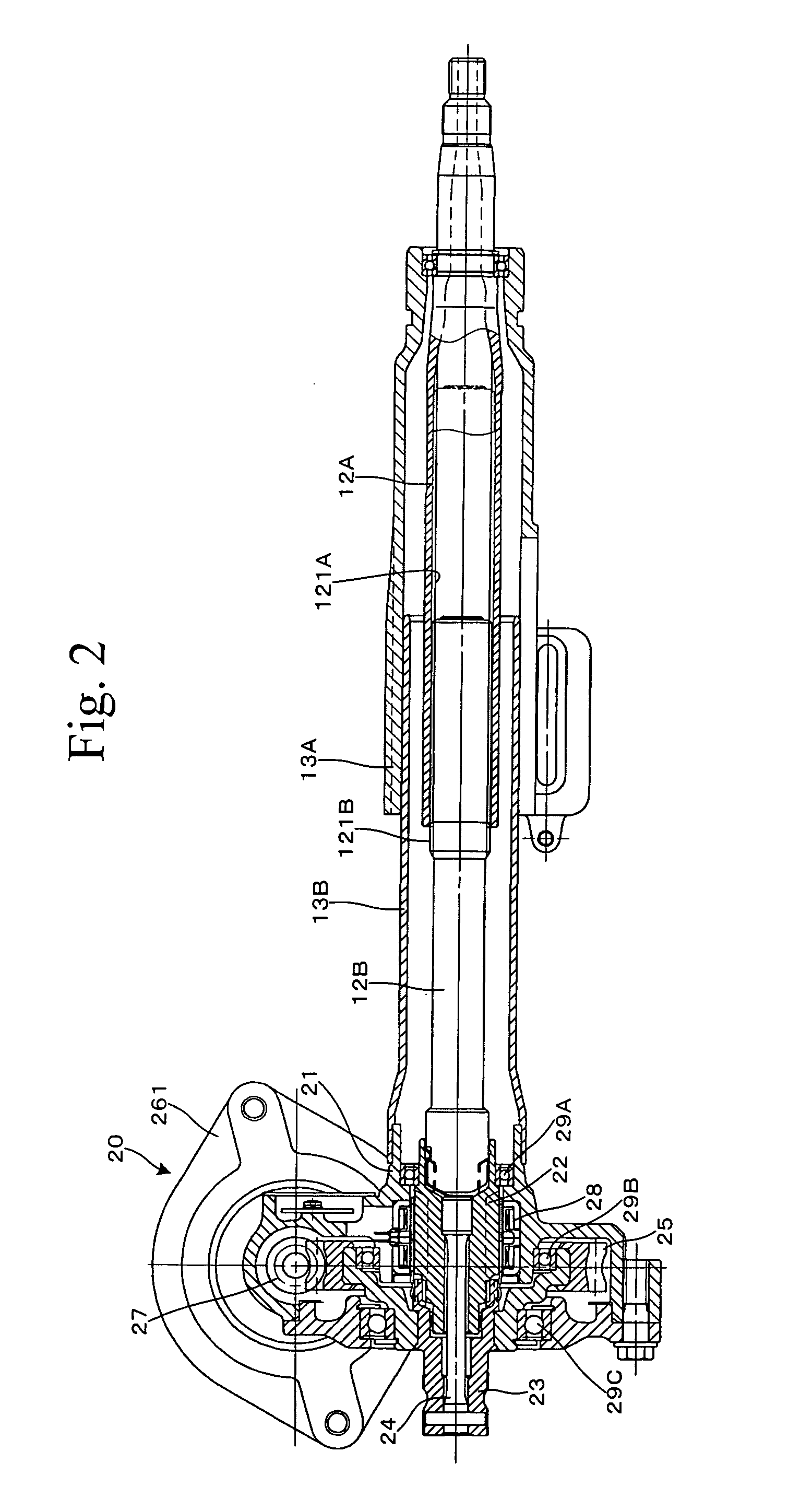
[0095] FIGS. 3(1) and (2) and FIGS. 4(1) to (3) show a coupled portion of a steering shaft according to a first embodiment of the present invention, and show an example in which it has been applied to a coupled portion between an inner shaft (upper steering shaft) 12B of FIG. 2, and an input shaft (lower steering shaft) 22 of an assist device 20. FIG. 3(1) is a longitudinal section showing the coupled portion between the inner shaft 12B and the input shaft 22, and FIG. 3(2) is a cross section taken on line A-A of FIG. 3(1). FIG. 4(1) is a cross section showing an input shaft 22 taken on line A-A of FIG. 3(1), FIG. 4(2) is a cross section showing a spring taken on line A-A of FIG. 3(1), and FIG. 4(3) is a cross section showing an inner shaft 12B taken on line A-A of FIG. 3(1).
[0096] As shown in FIGS. 3(1) and (2) and FIGS. 4(1) to 4(3), a side end portion ahead of the body (left side of FIGS. 3(1) and (2)) of the inner shaft 12B has been coupled to a side end portion in the rear of ...
second embodiment
[0108] Next, the description will be made of the second embodiment of the present invention. FIGS. 5(1) and (2) and FIGS. 6(1) to (3) show a coupled portion of a steering shaft according to the second embodiment of the present invention, FIG. 5(1) is a longitudinal cross section showing a coupled portion between the inner shaft 12B and the input shaft 22, and FIG. 5(2) is a cross section taken on line B-B of FIG. 5(1). FIG. 6(1) is a cross section showing the input shaft 22, taken on line B-B of FIG. 5(1), FIG. 6(2) is a cross section showing the spring and the columnar pin taken on line B-B of FIG. 5(1), and FIG. 6(3) is a cross section showing the inner shaft 12B taken on line B-B of FIG. 5(1). In the following description, only the structural portions and operations different from the above-described embodiments will be described, and repeated description will be omitted.
[0109] The second embodiment is an example in which the semi-circular projection 41 of the inner shaft 12B ha...
third embodiment
[0118] Next, the description will be made of the third embodiment of the present invention. FIGS. 7(1) and (2) and FIGS. 8(1) to (3) show a coupled portion of a steering shaft according to the third embodiment of the present invention, FIG. 7(1) is a longitudinal cross section showing a coupled portion between the inner shaft 12B and the input shaft 22, and FIG. 7(2) is a cross section taken on line C-C of FIG. 7(1). FIG. 8 (1) is a cross section showing the input shaft 22, taken on line C-C of FIG. 7(1), FIG. 8(2) is a cross section showing the spring and the sphere taken on line C-C of FIG. 7(1), and FIG. 8 (3) is a cross section showing the inner shaft 12B taken on line C-C of FIG. 7(1). In the following description, only the structural portions and operations different from the above-described embodiments will be described, and repeated description will be omitted.
[0119] The third embodiment is an example in which in place of the columnar pin 61 according to the second embodime...
PUM
 Abstract
Description
Claims
Application Information
 - R&D
- Intellectual Property
- Life Sciences
- Materials
- Tech Scout
- Unparalleled Data Quality
- Higher Quality Content
- 60% Fewer Hallucinations
Browse by: Latest US Patents, China's latest patents, Technical Efficacy Thesaurus, Application Domain, Technology Topic, Popular Technical Reports.
© 2025 PatSnap. All rights reserved.Legal|Privacy policy|Modern Slavery Act Transparency Statement|Sitemap|About US| Contact US: help@patsnap.com