

Collision detection system for vehicle
a detection system and vehicle technology, applied in the direction of instruments, force/torque/work measurement apparatus, tractors, etc., can solve the problems of increased cost, and difficulty in appropriately detecting collision load exerted at each part of the bumper
- Summary
- Abstract
- Description
- Claims
- Application Information
AI Technical Summary
Benefits of technology
Problems solved by technology
Method used
Image

Examples
first embodiment
(First Embodiment)
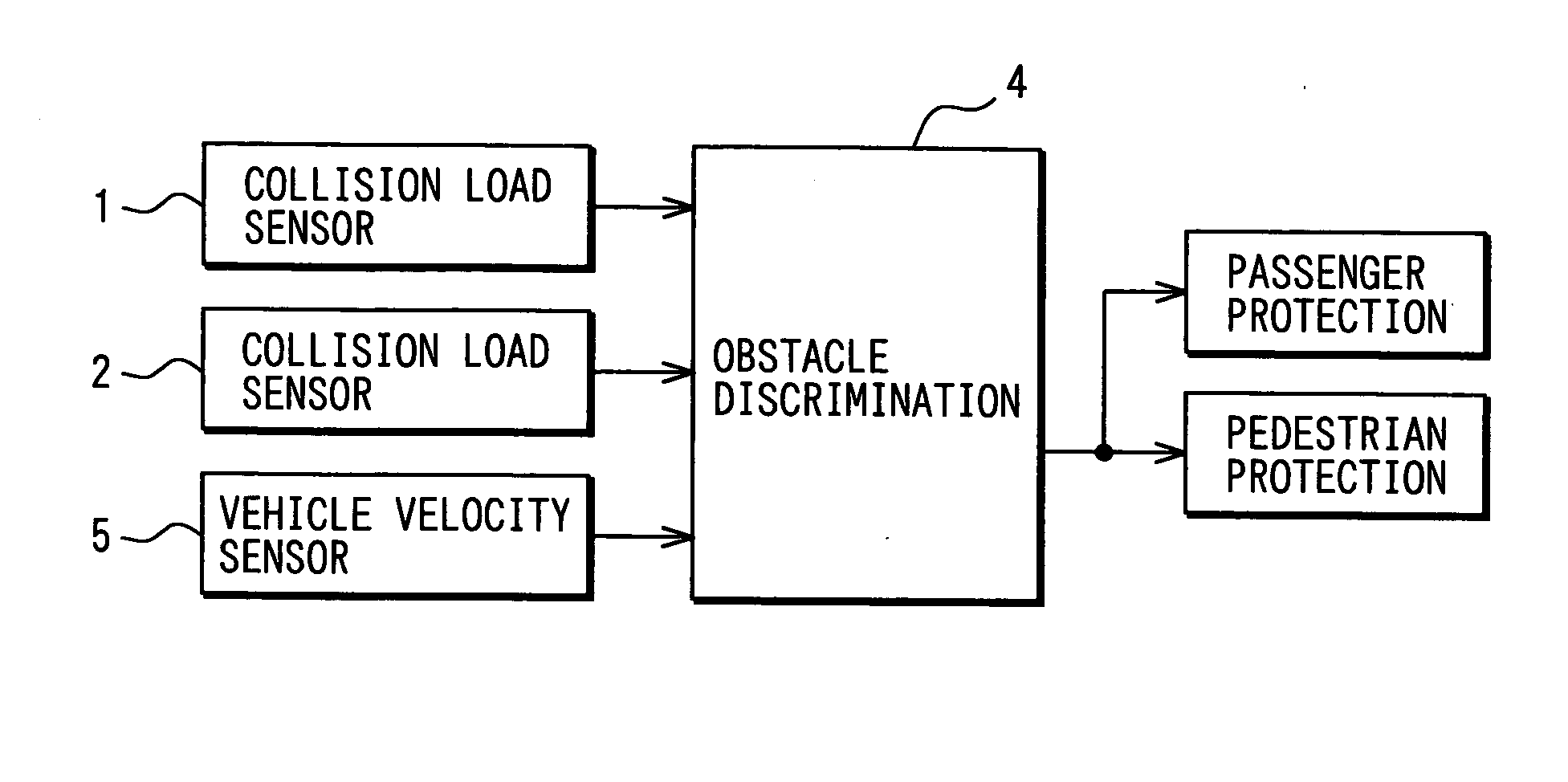
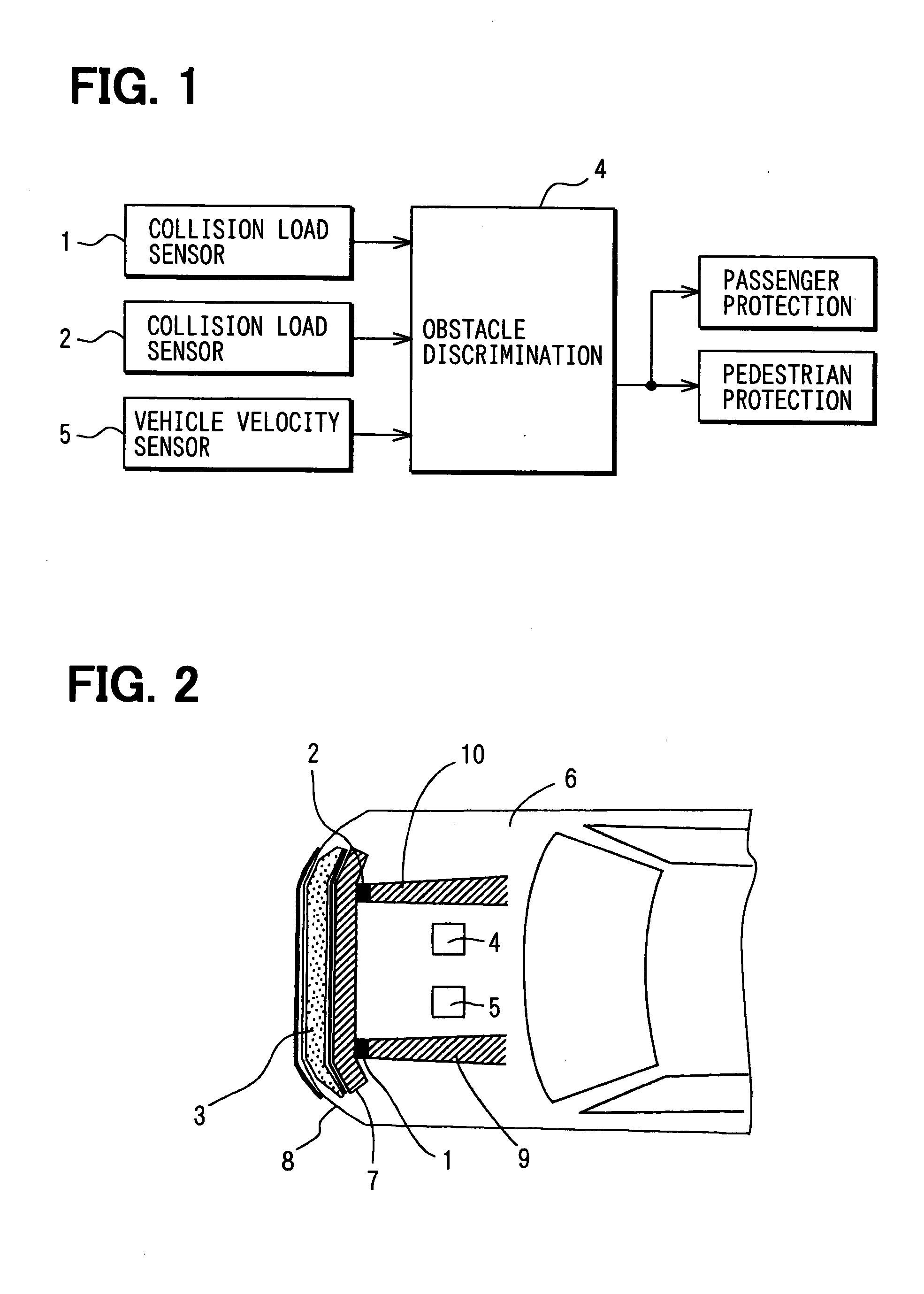
[0026] According to a first embodiment of the present invention, a collision detection system for a vehicle is suitably used to detect a collision load exerted at a bumper of the vehicle when an obstacle collides with the vehicle. Referring to FIG. 1, the collision detection system has two collision load detection units 1 and 2 (e.g., collision load sensors) for outputting signals corresponding to the collision load, a control unit 4 (e.g., signal processing circuit) for processing signals output by the collision load detection units 1 and 2, and the like.
[0027] The collision detection system is mounted between a bumper reinforce member 7 and side members 9, 10 of the vehicle. The bumper reinforce member 7 is positioned at a vehicle rear side of the bumper. The bumper includes a bumper cover 8 and a bumper absorber 3, which extend substantially in a vehicle width direction. The bumper cover 8 is positioned at a front end of the vehicle and fixed to a vehicle chass...
second embodiment
(Second Embodiment)
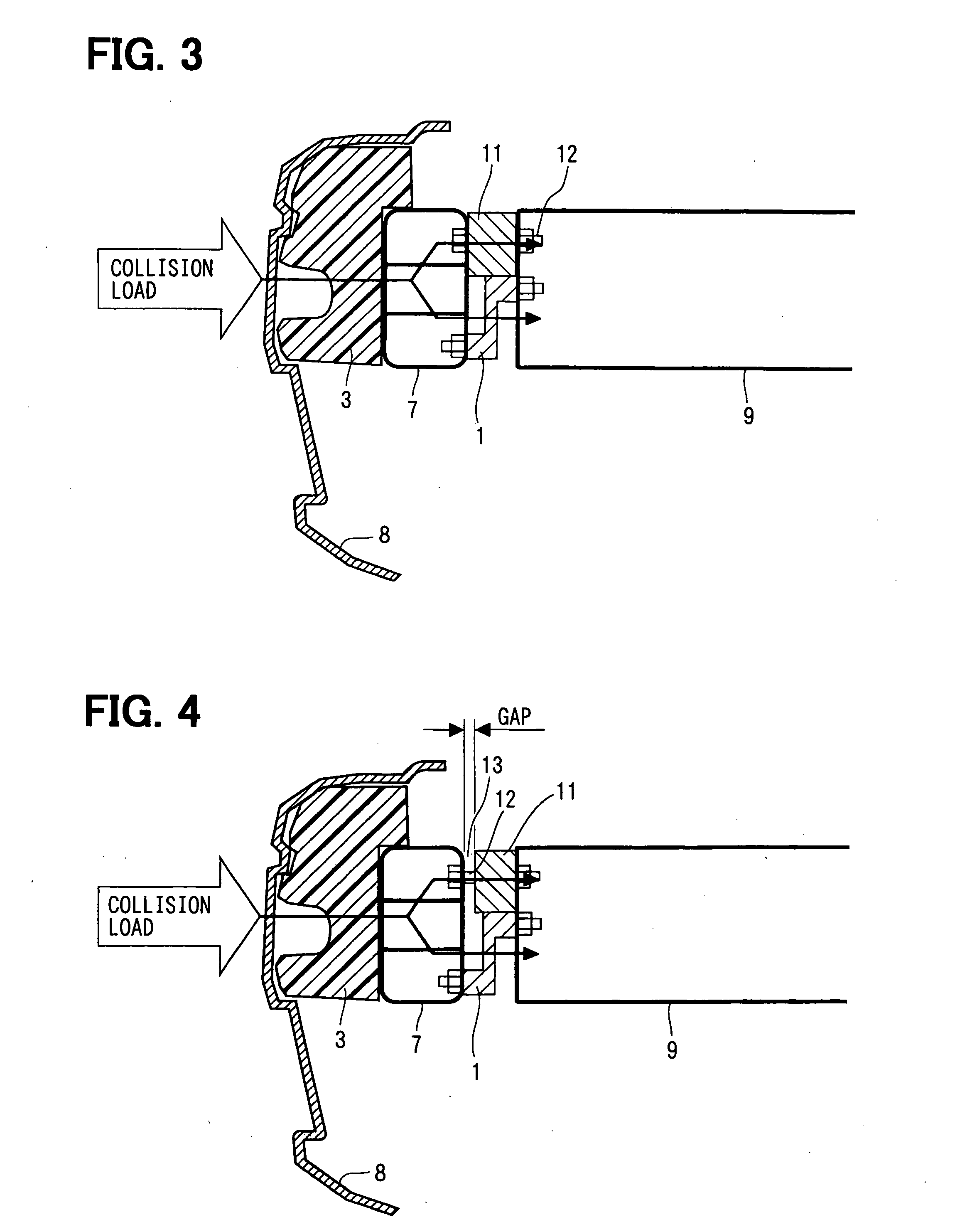
[0041] According to a second embodiment of the present invention, referring to FIG. 4, a gap 13 (without being provided in above-described first embodiment) is arranged between the rear end surface of the bumper reinforce member 7 and the collision load bypass member 11 to admit a position variation (including displacement and deformation) of the bumper reinforce member 7 toward the vehicle rear side.
[0042] According to this embodiment, the bolt 12 is inserted through the penetration holes which are respectively formed at the frond end of the side member 9 (or 10), the collision load bypass member 11 and the rear end of the bumper reinforce member 7, and engaged with the nuts or the like to be fastened with a play. In this case, the rear end surface of the collision load bypass member 11 contacts the front end surface of the side member 9 (or 10), while the gap 13 is arranged between a front end surface of the collision load bypass member 11 and the rear end surf...
third embodiment
(Third Embodiment)
[0050] A third embodiment of the present invention will be described referring to FIG. 7. In this case, one part (e.g., upper portion) of the front end of the side member 9, 10 protrudes toward the vehicle front side with respect to other part (e.g., lower portion) thereof, to be used as the collision load bypass member 11. In this case, the one part of the front end of the side member 9, 10 can be arranged to contact the bumper reinforce member 7, or spaced from it by the gap 13 (referring to the second embodiment) where the gap-maintaining member can be provided.
[0051] Alternatively, one part (e.g., upper portion) of the rear end of the bumper reinforce member 7 can also protrude toward the vehicle rear side with respect to other part (e.g., lower portion) thereof, to be used as the collision load bypass member 11. In this case, the one part of the rear end of the bumper reinforce member 7 can be arranged to contact the side member 9, 10, or spaced from it by th...
PUM
| Property | Measurement | Unit |
|---|---|---|
| distance | aaaaa | aaaaa |
| length | aaaaa | aaaaa |
| tension | aaaaa | aaaaa |
Abstract
Description
Claims
Application Information