Method of reducing electromagnetic interference and circuit connection device using the same

a technology of electromagnetic interference and circuit connection, applied in the direction of cross-talk/noise/interference reduction, transient suppressor details, printed circuit aspects, etc., can solve the problems of increasing the length of the harness, and increasing the electromagnetic interference. , to achieve the effect of efficient reduction of electromagnetic interferen

Inactive Publication Date: 2006-04-27
S PRINTING SOLUTION CO LTD
View PDF8 Cites 11 Cited by
  • Summary
  • Abstract
  • Description
  • Claims
  • Application Information

AI Technical Summary

Benefits of technology

[0017] The present general inventive concept provides an electromagnetic interference reducin

Problems solved by technology

A harmonic component of the signal transmitted through the harness is emitted, resulting in electromagnetic interference (EMI).
The EMI becomes more severe as the frequency of the transmitted signal increases and the length of harness increases.
The harmonic components emitted from the harnesses 122, 124, 126, and 128 have an adverse effect on peripheral electronic devices, and may cause a malfunction of the printer.
However, when a ferrite core is used, there are disadvantages in that the production cost of a device increases as much as the price of the ferrite core and the length of a harness should be extended according to how many times the harness is wound around the ferrite co

Method used


Image

  • Method of reducing electromagnetic interference and circuit connection device using the same
  • Method of reducing electromagnetic interference and circuit connection device using the same
  • Method of reducing electromagnetic interference and circuit connection device using the same

Examples


Embodiment Construction

[0033] Reference will now be made in detail to the embodiments of the present general inventive concept, examples of which are illustrated in the accompanying drawings, wherein like reference numerals refer to the like elements throughout. The embodiments are described below in order to explain the present general inventive concept while referring to the figures.

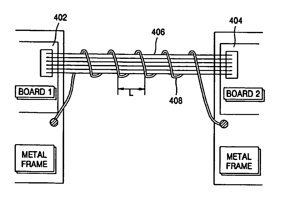
[0034]FIG. 4 is a diagram illustrating a circuit connection device according to an embodiment of the present general inventive concept. Referring to FIG. 4, the circuit connecting device includes a harness 406 to transmit a signal connecting two circuit boards 402 and 404 and a ground line 408 which is wound around the harness 406 at least once and is connected to a ground. As illustrated in FIG. 4, the ground line 408 is grounded through a metal frame in which the circuit boards 402 and 404 are installed.

[0035] The ground line 408 is wound around the harness 406 at least once. A space L between turns of the ground line 40...


PUM


Abstract

A device and a method of reducing electromagnetic interference resulting from a harmonic wave produced by a signal transmitted through a harness. The method includes winding a conductive wire at least once around the harness, and grounding at least one end of the conductive wire. Accordingly, the electromagnetic interference reducing method is capable of reducing electromagnetic interference without any side effects by using a low cost and a simple ground line.

Description

CROSS-REFERENCE TO RELATED APPLICATIONS [0001] This application claims the priority under 35 U.S.C. § 119 of Korean Patent Application No. 2004-78741, filed on Oct. 4, 2004, in the Korean Intellectual Property Office, the disclosure of which is incorporated herein in its entirety by reference. BACKGROUND OF THE INVENTION [0002] 1. Field of the Invention [0003] The present general inventive concept relates to signal transmission of an electronic device, and more particularly, to a method of reducing an effect of electromagnetic waves which are emitted from a harness that transmits a signal. [0004] 2. Description of the Related Art [0005] A high frequency signal flowing along a transmission path radially emits an electromagnetic field. The strength of the electromagnetic field is directly proportional to the power of the signal. [0006] In an electronic device, a plurality of signal lines are used in a harness connected between two connectors in order to electrically connect circuit pa...

Claims


Application Information

Patent Timeline
IPC IPC(8): H05K1/11
CPCH05K1/0216H05K1/148H05K9/0066H05K2201/10287H05K9/00
Inventor PARK, KUN-YOUNG
Owner S PRINTING SOLUTION CO LTD
Why Eureka
Try Eureka