Light modulating plate, backlight assembly having the same and display device having the same

a technology of backlight assembly and light modulating plate, which is applied in the direction of instruments, waveguides, lighting and heating apparatus, etc., can solve the problems of complicated manufacturing process of backlight assembly, and achieve the effects of improving the optical characteristics of secondly scattered light, and improving the optical characteristics of ligh

Inactive Publication Date: 2006-04-27
SAMSUNG DISPLAY CO LTD
View PDF7 Cites 25 Cited by
  • Summary
  • Abstract
  • Description
  • Claims
  • Application Information

AI Technical Summary

Benefits of technology

[0008] A light modulating plate in accordance with an embodiment of the present invention includes a light modulating layer and a light characteristics improving member. The light modulating layer includes a foam layer to modulate a light. The light characteristics improving member is integrally formed with the light modulating layer to improve optical characteristics of the light that has passed through the light modulating layer.
[0009] A backlight assembly in accordance with an aspect of the present invention includes a lamp, a light modulating plate and a light characteristics improving member. The lamp generates light. The light modulating plate includes a foam layer to scatter the light to modulate the light generated from the lamp. The light characteristics improving member is integrally formed with the light modulating plate to improve optical characteristics of the light that has passed through the light modulating layer.
[0010] A backlight assembly in accordance with another aspect of the present invention includes a lamp, a first foam layer, a diffusion layer, a second foam layer and a light characteristics improving layer. The lamp generates light. The first foam layer firstly scatters the light generated from the lamp. The diffusion layer is integrally formed with the first foam layer to diffuse the firstly scattered light. The second foam layer is integrally formed with the diffusion layer to secondly scatter the diffused light. The light characteristics improving layer is integrally formed with the second foam layer to improve optical characteristics of the seco

Problems solved by technology

However, when the number of the optical sheets and a size of each of the optical sheet

Method used


Image

  • Light modulating plate, backlight assembly having the same and display device having the same
  • Light modulating plate, backlight assembly having the same and display device having the same
  • Light modulating plate, backlight assembly having the same and display device having the same

Examples


Embodiment Construction

[0029] It should be understood that the exemplary embodiments of the present invention described below may be varied and modified in many different ways without departing from the inventive principles disclosed herein, and the scope of the present invention is therefore not limited to these particular following embodiments. Rather, these embodiments are provided so that this disclosure will be thorough and complete, and will fully convey the concept of the invention to those skilled in the art by way of example and not of limitation.

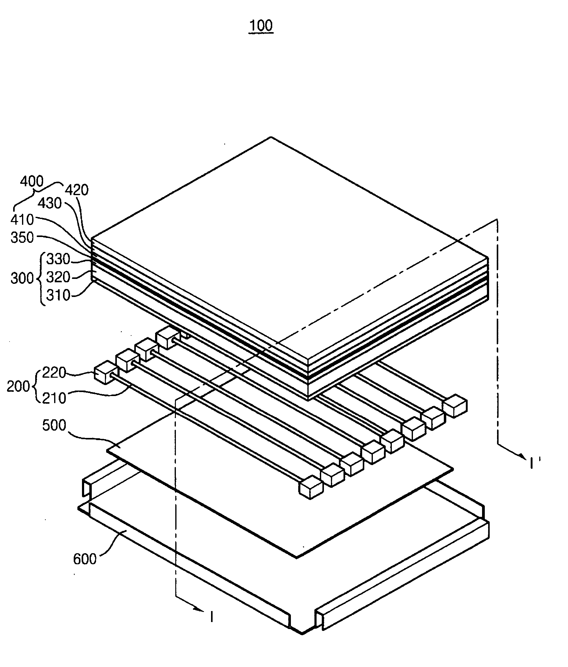
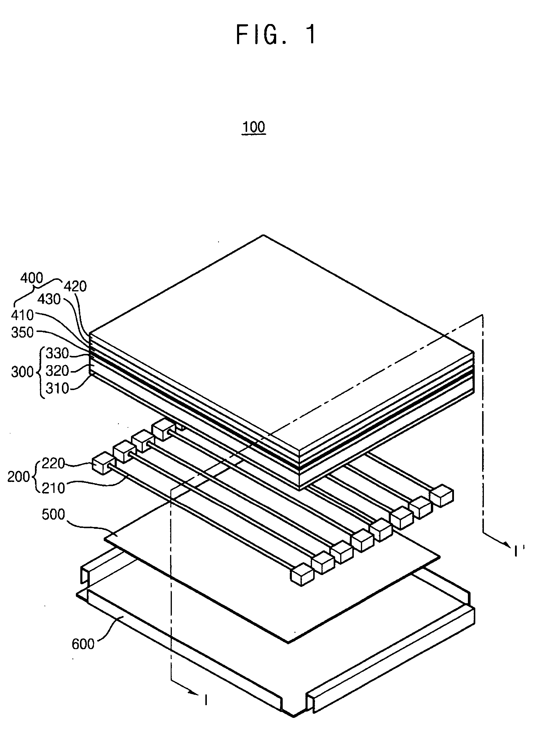
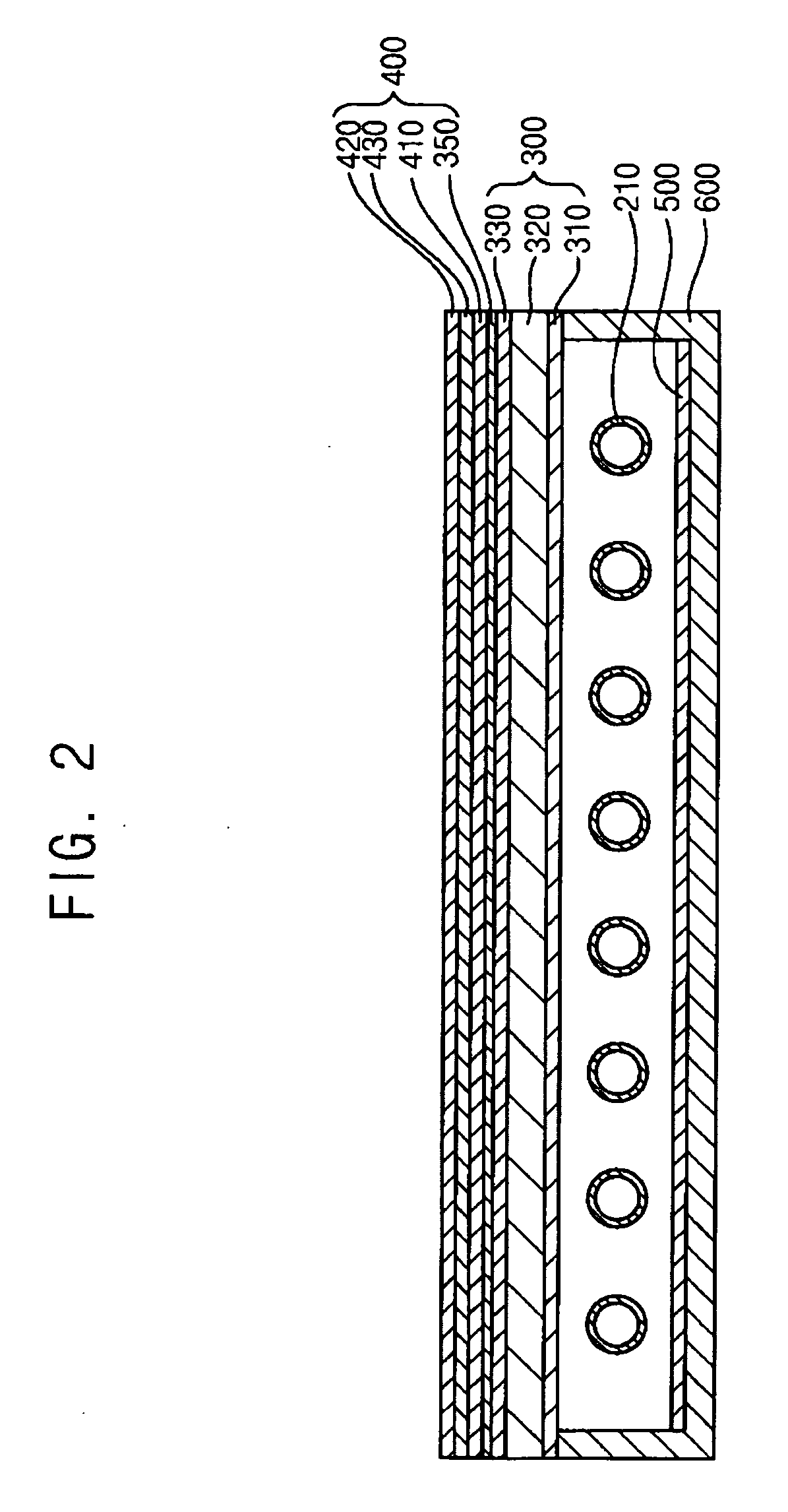
[0030]FIG. 1 is an exploded perspective view showing a backlight assembly in accordance with an exemplary embodiment of the present invention. FIG. 2 is a cross-sectional view taken along a line I-I′ shown in FIG. 1. The backlight assembly 100 includes a lamp unit 200, a light modulating plate 300, a light characteristics improving member 400, a reflecting plate 500 and a receiving container 600. The lamp unit 200 includes a plurality of lamps 210 that ...


PUM


Abstract

In a light modulating plate, a backlight assembly having the light modulating plate and a display device having the light modulating plate, the light modulating plate includes a light modulating layer and a light characteristics improving member. The light modulating layer includes a foam layer to modulate a light. The light characteristics improving member is integrally formed with the light modulating layer to improve optical characteristics of the light that has passed through the light modulating layer. Therefore, the backlight assembly is easily fabricated, and an image display quality is improved.

Description

CROSS-REFERENCE TO RELATED APPLICATIONS [0001] The present application claims priority from Korean Patent Application No. 2004-86361, filed on Oct. 27, 2004, Korean Patent Application No. 2004-85747, filed on Oct. 26, 2004, and Korean Patent Application No. 2004-85750, filed on Oct. 26, 2004, the disclosure of which is hereby incorporated herein by reference in their entireties. BACKGROUND OF THE INVENTION [0002] 1. Field of the Invention [0003] The present invention relates to a light modulating plate, and a backlight assembly and a display device having the light modulating plate. More particularly, the present invention relates to a light modulating plate capable of being easily fabricated and exhibiting an improved image display quality, and a backlight assembly and a display device containing the light modulating plate. [0004] 2. Description of the Related Art [0005] A liquid crystal display (LCD) device has various advantageous characteristics in thickness, durability, weight,...

Claims


Application Information

Patent Timeline
IPC IPC(8): F21V7/04F21V5/00
CPCG02B5/0242G02B5/0247G02B5/0278G02B6/005G02B6/0055Y10S385/901G02F1/133604G02F1/133606G02F2001/133507G02F2001/133607Y10T428/10G02B6/0081C09K2323/00G02F1/133507G02F1/133607
Inventor HA, JU-HWAKIM, JIN-SOOKIM, HEU-GONJUNG, JAE-HO
Owner SAMSUNG DISPLAY CO LTD
Why Eureka
Try Eureka