Bone mill and template

a bone mill and template technology, applied in the field of bone mills and templates, can solve the problems of template occupying additional space in the cutting area, non-trivial operation, and high operating costs of elaborate mechanical devices, and achieve the effects of less bone, accurate bone removal, and limited bone removal

Inactive Publication Date: 2006-04-27
MICROAIRE SURGICAL INSTR
View PDF26 Cites 190 Cited by
  • Summary
  • Abstract
  • Description
  • Claims
  • Application Information

AI Technical Summary

Benefits of technology

[0009] The present invention provides templates and milling devices for milling bone to a desired, standardized size and shape. The invention allows a surgeon to accurately remove a volume of bone of a defined, three-dimensional shape, thereby creating a space in or on the bone for placement of an endoprosthetic device that fits the space. The templates of the present invention are used as a guide to limit the extent of bone removal by a milling device, i.e. to delimit (set the boundaries of) the depth, lateral dimensions and shape of the volume of bone that is removed. Further, use of the templates and milling devices of the present invention allows the removal of less bone than in known, prior art procedures.

Problems solved by technology

While such replacement surgery is a vast improvement over the prospect of pain and immobility due to a diseased knee, the operation is non-trivial, typically requiring a 10-12 inch incision, extensive resectioning of the bone, and weeks or months of rehabilitation.
While some technologies do exist for guiding the cutting and milling of the bone to ensure a correct fit of the prostheses and alignment of the knee bones, many involve very elaborate mechanical devices that are expensive and very complicated to operate.
However, the template comprises two portions, one of which is movable and thus relatively complex, and which causes the template to take up additional space in a cutting area where space is very limited.
However, in this case the depth of milling is controlled by a relatively complex system involving a separate attachment that serves as a depth monitor.
Such technologies do not provide a simple system for controlling both the two dimensional boundaries and the depth of milling.
They do little to decrease the time required for carrying out the milling procedure, and may be so complex as to dissuade surgeons from attempting their use.
The prior art has thus far failed to supply technology that allows accurate, three-dimensional milling of bone surfaces to a desired size and shape in a straightforward, accurate and affordable manner.

Method used


Image

  • Bone mill and template
  • Bone mill and template
  • Bone mill and template

Examples


Embodiment Construction

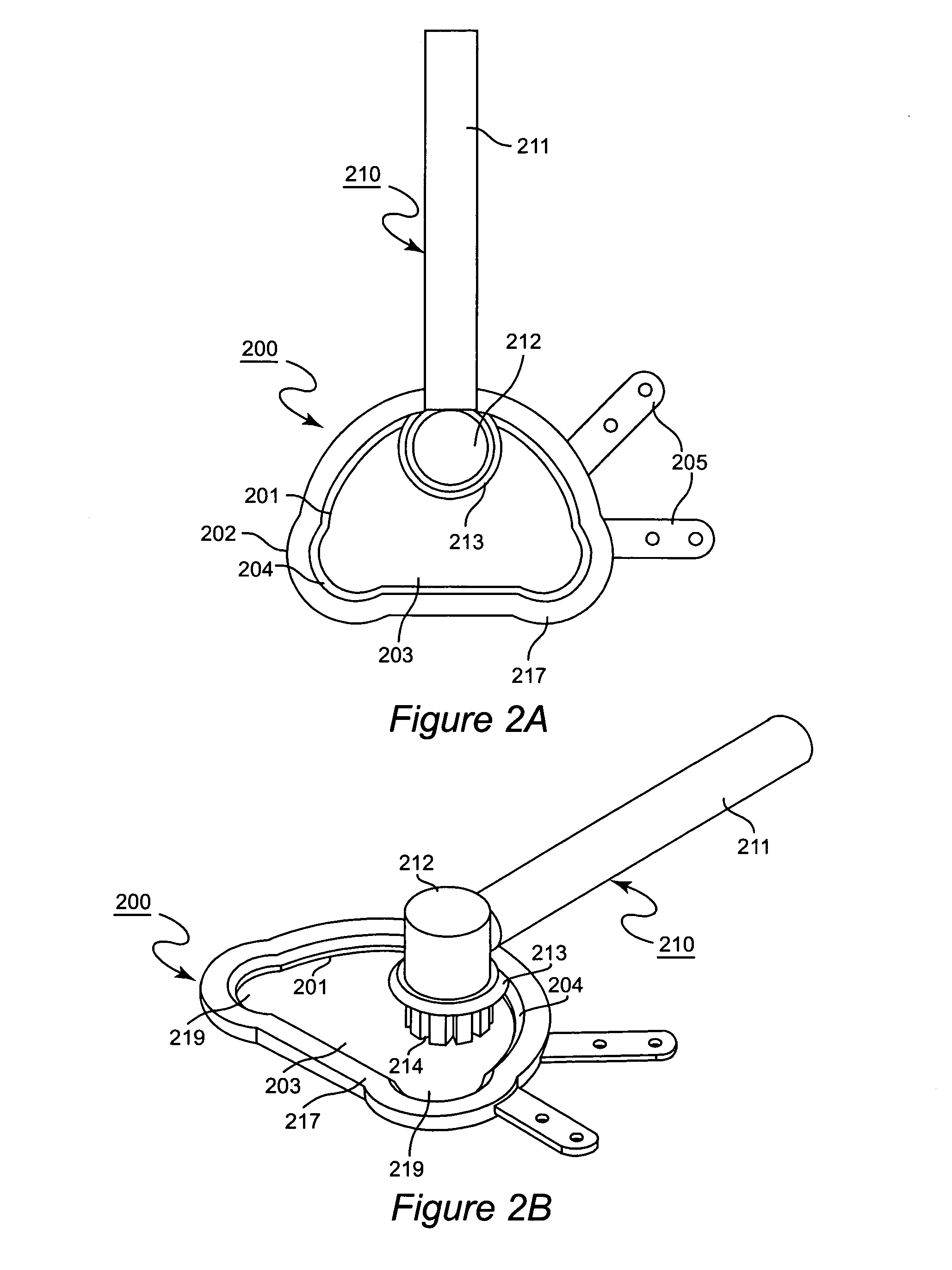
[0035] A top perspective view of a template and milling device of the present invention is shown in FIG. 2A. Referring to the Figure, template 200 is a frame with a top surface 217 and a bottom surface 216 (not shown; see FIG. 3). The frame of the template 200 is formed in a roughly hemispherical shape and bounded with an inner edge or rim (internal sidewall) 201 which defines an inner perimeter of the template, and an outer edge or rim (outer sidewall) 202 that defines the outer perimeter of the template. Inner rim 201 further defines a peripheral boundary of a central open space, central opening 203. Guide track or groove 204 runs along the entire length of the inner edge 201 of template 200. The frame is typically of a thickness of about 0.05 inches. Attachment means (e.g. attachment tabs 205) extend outward horizontally from template 200 and contain holes 206. In a preferred embodiment, attachment tabs 205 are bendable and may be scored to facilitate bending. The tabs are capabl...


PUM


Abstract

Bone mills and templates for use in during bone resectioning is provided. The templates have a flat upper surface or an interior track, and the mill has an edge that rides on top of the upper surface or within the groove. The template thus guides the mill during bone resectioning, delimiting the area and depth of the bone that is removed. Additional bone mills with supports and frames that control the depth of milling are also provided.

Description

BACKGROUND OF THE INVENTION [0001] 1. Field of the Invention [0002] The invention generally relates to a mill and template for use during bone resectioning. In particular, the invention provides a template with an interior track that guides the mill during resectioning of the bone. [0003] 2. Background of the Invention [0004] Knee “replacement” surgery is becoming more and more common as a result of increased longevity and the attendant increase in geriatric related diseases such as osteoarthritis. The term “replacement” is a misnomer in that the entire knee is not replaced. Rather, diseased portions of the tibial and femoral condyles of the knee are removed and replaced with endoprosthetic (metal and / or polymer) inserts. While such replacement surgery is a vast improvement over the prospect of pain and immobility due to a diseased knee, the operation is non-trivial, typically requiring a 10-12 inch incision, extensive resectioning of the bone, and weeks or months of rehabilitation....

Claims


Application Information

Patent Timeline
Patent Type & Authority Applications(United States)
IPC IPC(8): A61B17/00
CPCA61B17/1615A61B17/1675A61B17/1764A61B17/32002A61B2017/1602A61B2017/320052
Inventor FARD, MIKE
Owner MICROAIRE SURGICAL INSTR
Why Eureka
Try Eureka