Wireless sensors in roll covers

a sensor and wireless technology, applied in the field of industrial rolls, can solve the problems of uneven surface characteristics of poor quality paper, increasing difficulty in managing electrical connections, and crushing of fibers as well as holes in the resulting paper produ

Active Publication Date: 2006-05-04
STOWE WOODWARD
View PDF13 Cites 46 Cited by
  • Summary
  • Abstract
  • Description
  • Claims
  • Application Information

AI Technical Summary

Problems solved by technology

Excessive pressure and / or width can cause crushing of fibers as well as holes in the resulting paper product.
Additionally, the magnitude and area of pressure applied to the sheet may be uneven along or across the length of the roll, often resulting in paper of poor quality having uneven surface characteristics.
As the number of sensors increase, these electrical connections may become increasingly difficult to manage.
For example, wire routing can be especially difficult in the case of variable crown rolls.
In addition, routing multiple wires through the layers of the roll cover may weaken the integrity of the cover.
However, if more than one sensor is in the nip at a time, it may become difficult, if not impossible, to tell which signal is coming from which sensor.
For example, for temperature measurements there is a negligible cyclical pulse so it is nearly impossible to distinguish different temperature sensors using only two wires.
In all cases, wire routing may be a difficult task.

Method used


Image

  • Wireless sensors in roll covers
  • Wireless sensors in roll covers
  • Wireless sensors in roll covers

Examples


Embodiment Construction

[0027] The present invention will now be described more fully hereinafter, in which preferred embodiments of the invention are shown. This invention may, however, be embodied in different forms and should not be construed as limited to the embodiments set forth herein. Rather, these embodiments are provided so that this disclosure will be thorough and complete, and will fully convey the scope of the invention to those skilled in the art. In the drawings, like numbers refer to like elements throughout. Thicknesses and dimensions of some components may be exaggerated for clarity.

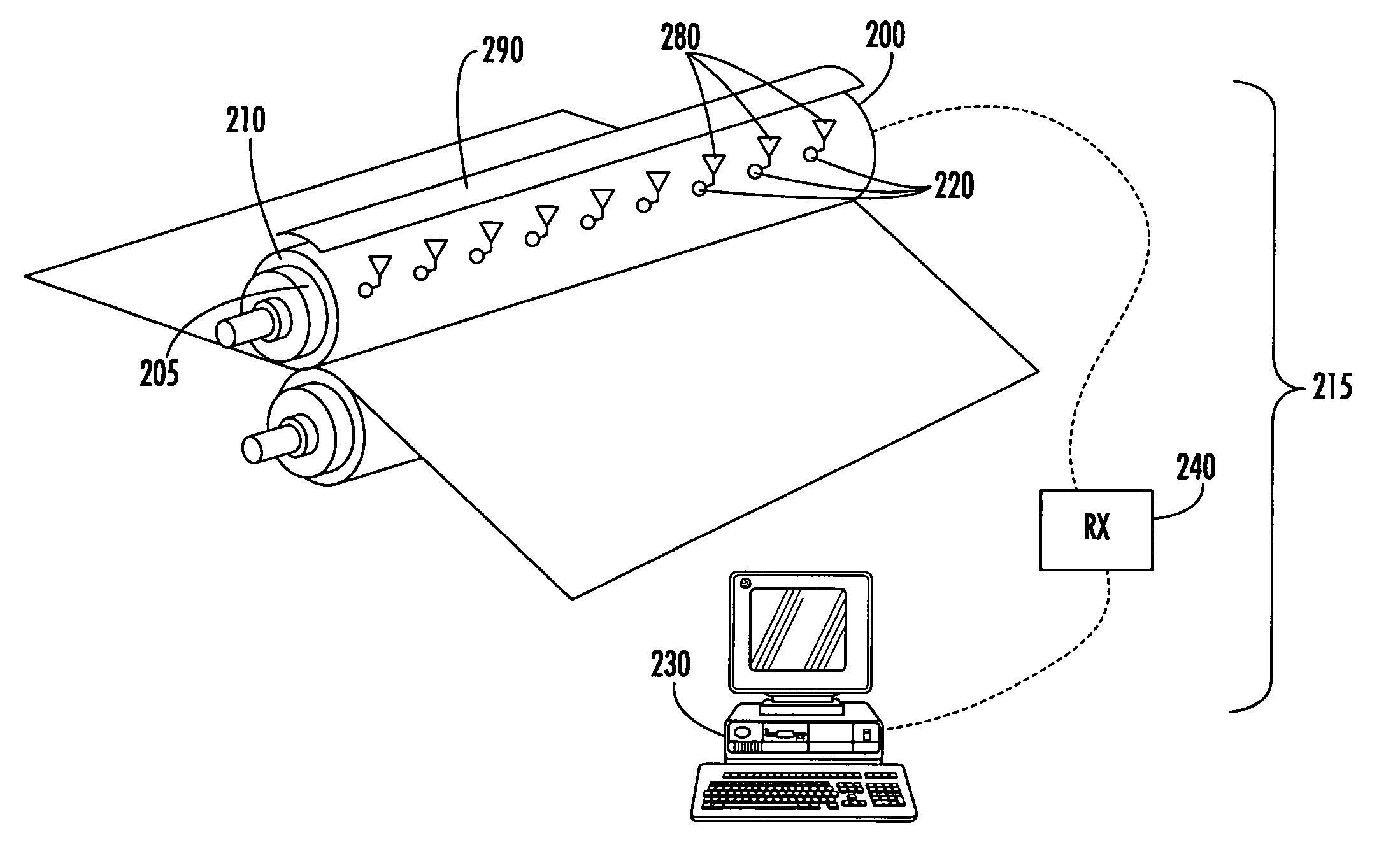
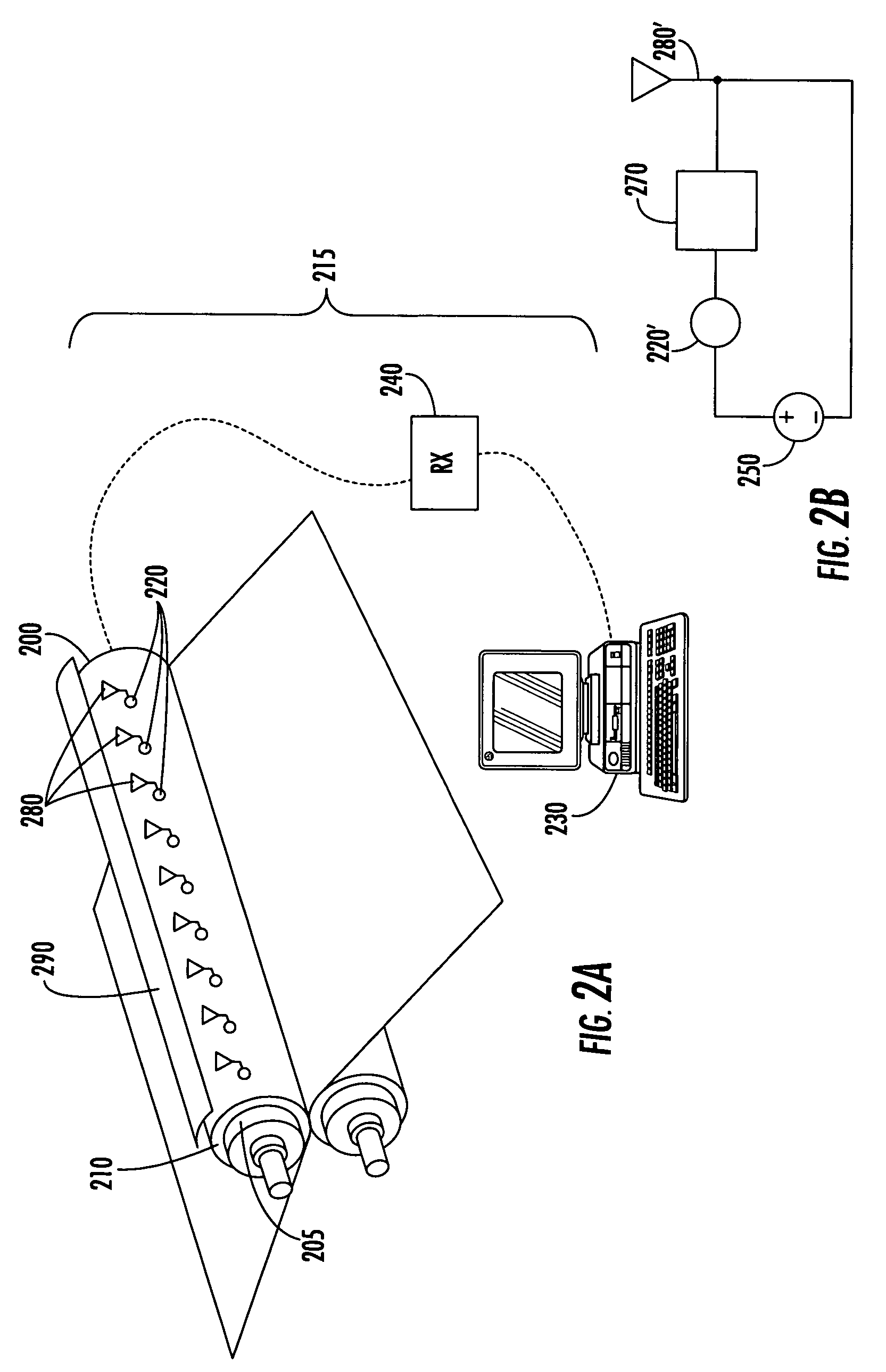
[0028] Referring now to the figures, FIG. 2A illustrates a system for measuring operating parameters in a nip roll according to embodiments of the present invention. As shown in FIG. 2A, the nip roll 200 includes a cylindrical shell or core 205 and a cover 210 (typically formed of one or more polymeric materials) that encircles the shell 205. A sensing system 215 for sensing pressure, temperature, strain, moi...


PUM

PropertyMeasurementUnit
frequencyaaaaaaaaaa
lengthaaaaaaaaaa
temperatureaaaaaaaaaa

Abstract

An industrial roll includes: a substantially cylindrical shell having an outer surface; a polymeric cover circumferentially overlying the shell outer surface; and a sensing system. The sensing system includes: a plurality of sensors embedded in the cover, each sensor configured to sense a data parameter; and a plurality of wireless transceivers, each transceiver connected to a respective sensor and embedded in the cover adjacent thereto. Each wireless transceiver is configured to transmit data signals from the respective sensor. Related methods and systems are also discussed.

Description

FIELD OF THE INVENTION [0001] The present invention relates generally to industrial rolls, and more particularly to rolls for papermaking. BACKGROUND OF THE INVENTION [0002] Cylindrical rolls may be utilized in a number of industrial applications, especially those relating to papermaking. Such rolls may typically be employed in demanding environments in which they can be exposed to high dynamic loads and temperatures. As an example, in a typical paper mill, rolls can be used not only for transporting a fibrous web sheet between processing stations, but also, in the case of press section and calender rolls, for processing the web sheet itself into paper. [0003] In the press section of the papermaking process, two or more cooperating rolls press the fibrous web as it travels on felts between the rolls. The “nip” is the contact region between two adjacent rolls through which the paper web passes. Each roll is typically constructed from a metallic shell covered by a polymeric cover. The...

Claims


Application Information

Patent Timeline
Patent Type & Authority Applications(United States)
IPC IPC(8): G01L5/00F16C13/00D21FG01L5/04
CPCG01L5/0085G01L5/045G01L5/047G01K1/026G01K1/024
Inventor MOORE, ROBERT HUNTERGUSTAFSON, ERIC J.DANZLER, FRANZLUTZ, ANDREAS
Owner STOWE WOODWARD
Why Eureka
Try Eureka