Wire harness construction

a wire harness and construction technology, applied in the direction of insulated conductors, cables, conductors, etc., can solve the problems of low rigidity of wire harnesses, difficult operation of apertures, and inability to pull wire harnesses into space, and achieve smooth deformation, smooth bend, and successful protection of wire harnesses

Inactive Publication Date: 2006-05-04
SUMITOMO WIRING SYST LTD
View PDF4 Cites 32 Cited by
  • Summary
  • Abstract
  • Description
  • Claims
  • Application Information

AI Technical Summary

Benefits of technology

[0036] The surplus length portion of the wire harness, onto which the caterpillar-shaped protector is fitted, can smoothly bend, and therefore, can smoothly deform when being pulled out toward the body side or pulled into of the opening/closing member in response to the opening/closing operation of the opening/closing member, and can follow the extending and contracting operations of the wire harness. Further, since the outer peripheral surface of the wire harness is covered by connecting portions and a large number of small piece portions, the wire harness may be prevented from directly contacting a panel when following the opening/closing operation of the opening/closing member, resulting in the successful protection of the wire harness.
[0037] Further, since the surplus length portion of the wire harness may be supported by the caterpillar-shaped protector alone in both a bending condition and a condition extended from the bending condition by simply attaching the caterpillar-shaped protector, it is sufficient to provide a space allowing the surplus length portion to bend and deform, thus eliminating the need to separately prepare a surplus length absorbing space.
[0038] In this configuration, extension and contraction of the wire harness are absorbed by the deformation of the surplus length portion of the wire harness. The portion of the wire harness located at a point closer to the body side than the surplus length portion is attached by the straight tubular protector and moves without creating slack in the w

Problems solved by technology

However, passing the wire harness W/H through the aperture 1b is a very difficult operation.
However, in the above-described configuration, since the wire harness is simply formed from a group of electric wires bundled together by taping, the rigidity of the wire harness is low.
Therefore, there is a risk that the wire harness is not pulled into space 1c successfully when the door is closed.
In this case, the wire harness is hung by gravity between the body and the door, which may jam the wire harness therebetween.
Although the above-noted problems described in JP H10-934 are partially solved in JP H10-16672, other problems occur.
On the other hand, insufficient space can make the

Method used


Image

  • Wire harness construction
  • Wire harness construction
  • Wire harness construction

Examples


first embodiment

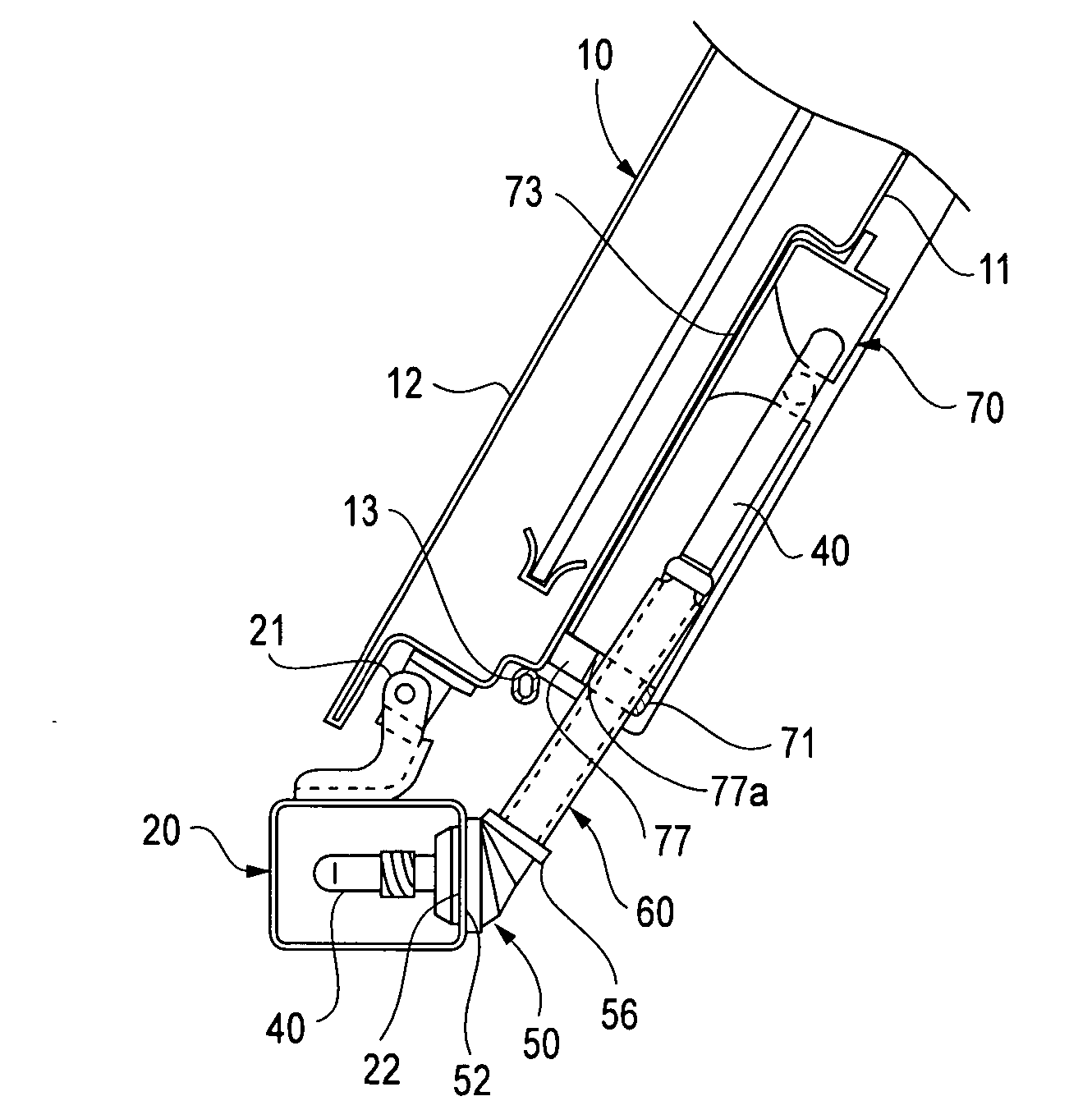
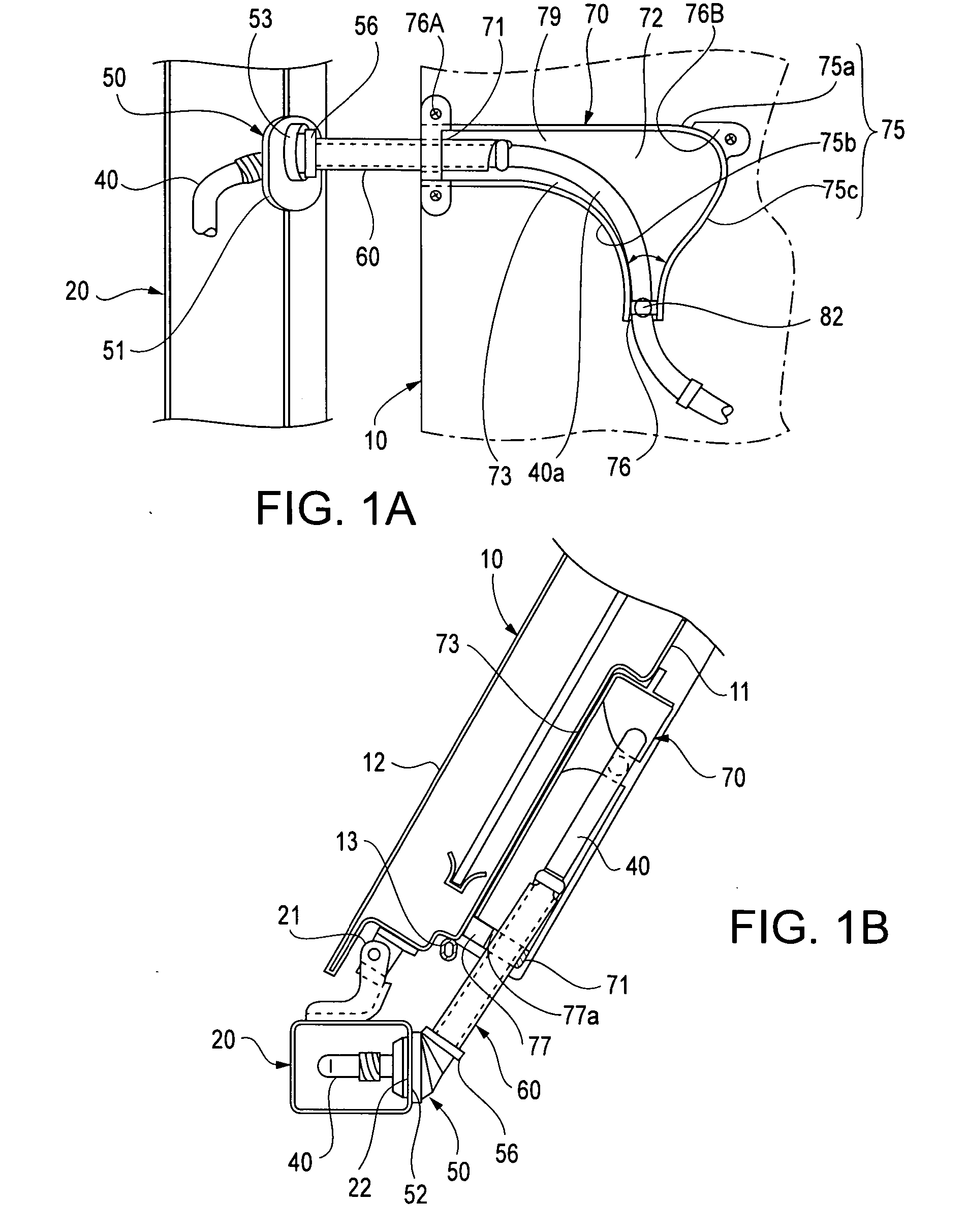
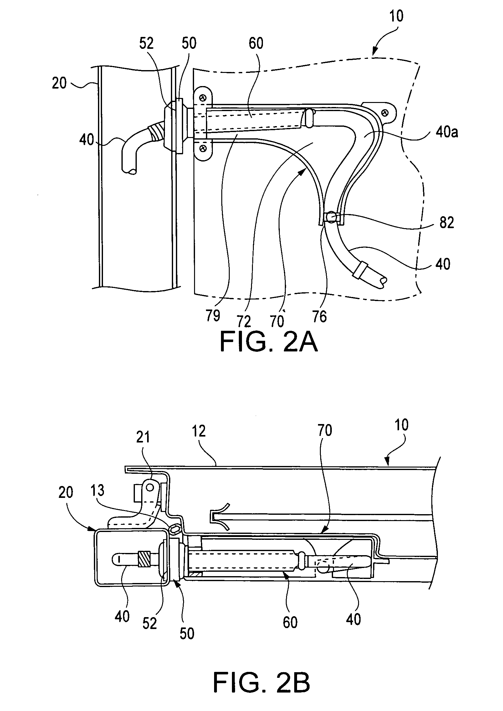
[0079] The embodiments of the present invention are explained in detail in the following in reference to the above-described drawings. FIGS. 1 through 6 illustrate the present invention. Wire harness (i.e., door harness) 40 mounted on side door 10 (hereinafter referred to as door 10) extends to body 20 of a vehicle. FIGS. 1A and 1B illustrate door 10 in an open position and FIGS. 2A and 2B illustrate door 10 in a closed position.

[0080] Outer panel 12 and inner panel 11 are connected on door 10. Protector 70 is provided on the passenger compartment side of the door 10 toward the body side of inner panel 11. Protector 70 may be formed of any suitable material such as, for example, a resin material; and protector 70 may be fixed on the passenger compartment side of the door 10. A door trim (no figure) is also attached to inner panel 11. On door 10, a body side end face of inner panel 11 is connected to body 20 by hinge 21. Door 10 is thus rotatably connected around hinge 21.

[0081] Wir...

third embodiment

[0095]FIG. 11 illustrates the present invention. Clamp 182 may be formed integrally and in one piece of any suitable material such as, for example, an elastic resin. Band 182a is formed of two halves, an upper half and a lower half, which may be opened and closed. Connecting portion 182h forms a thin formed hinge; and an upper half of band 182a is configured to rotate around connecting portion 182h. Male and female hook portions 182g and 182f, respectively, may be connected by mating with each other, sandwiching wire harness 40 therebetween. As a result, an easy assembly of wire harness 40 may be achieved. 182j indicates a spacer that has a thin planar shape facing downward and has a spring force; 182j absorbs margins of manufacturing error of protector 70 and clamp 182, eliminating backlash between clamp 182 and protector 70, while avoiding fixation in a rotating direction. Spacer 182j serves as a spacer that keeps a predetermined distance between wire harness 40 and a wall of prot...

fourth embodiment

[0096]FIGS. 12A, 12B, 13A, 13B, 14-16, 17A, 17B, and 17C illustrate the present invention. Wire harness 40 is mounted within inner panel 111 and its ends are connected to predetermined electronic components via connectors (not shown) attached to its ends. Wire harness 40 passes through a passenger compartment side of inner panel 111 and has protector 160 attached to a side where wire harness 40 is pulled out toward body 20. Wire harness 40 has grommet 50 fixed onto one end. Wire harness 40 having protector 160 and grommet 50 attached is pulled out from a point closer to the passenger compartment side than the weather strip on the body side surface of inner panel 111, and grommet 50 is fixedly inserted into attachment hole 22 of body 20.

[0097] As shown in FIG. 14, protector 160 connects a bendable caterpillar-shaped protector 161 to straight tubular protector 162 in a longitudinal direction. Protector 160 may formed integrally and in one piece; and protector 160 may formed of any sui...


PUM


Abstract

A wire harness is slidably arranged between a vehicle body and an opening/dosing member of the vehicle. A grommet is fitted onto one end of a wire harness, which is arranged in the opening/closing member and is pulled out toward the vehicle body. The grommet has a diaphragm portion that can swing, extend and contract. A tube having a predetermined length is fitted onto the wire harness. A first end of the tube is fitted onto the grommet, while a second end is fixed to the wire harness, so that the tube can be slidably received in a guiding portion provided in the opening/closing member. A surplus length portion is provided in the wire harness, which is pulled out from the tube, so that the wire harness can follow opening/closing operations of the opening/closing member. The surplus length portion is received in the surplus length absorbing space provided in the guiding portion, while the wire harness is locked onto the opening/closing member at an exit of the surplus length absorbing space.

Description

CROSS-REFERENCE TO RELATED APPLICATIONS [0001] The present disclosure relates to subject matter contained in priority Japanese Application Nos. 2004-305681 filed on Oct. 20, 2004, 2004-305693, filed on Oct. 20, 2004, 2004-307447, filed on Oct. 21, 2004, and 2004-305678, filed on Oct. 20, 2004, the entire content of which are expressly incorporated by reference herein. BACKGROUND OF THE INVENTION [0002] 1. Field of the Invention [0003] The present invention relates to a wire harness construction provided between a vehicle body and an opening / closing member of the vehicle such as, for example, a door or a trunk lid. [0004] 2. Description of Related Art [0005] An opening / closing member of a vehicle is attached to a vehicle by a hinge in a manner enabling easy opening and closing of the opening / closing member. Such members include doors, such as side-doors and rear doors, and other opening / closing members, such as trunk lids. If there are electric components provided in the opening / clos...

Claims


Application Information

Patent Timeline
IPC IPC(8): H01B7/00
CPCB60R16/0207
Inventor FUJITA, TETSUYA
Owner SUMITOMO WIRING SYST LTD
Why Eureka
Try Eureka