Variable air volume system including BTU control function

a variable air volume and control function technology, applied in the field of variable air volume systems, can solve the problems of sudden increase in the temperature of the supply air, uncomfortable temperature swings within the individual zones, and significant temperature swings in the vav system utilizing an on/off heating or cooling unit, so as to improve indoor air quality, save energy costs, and improve environmental comfort

Inactive Publication Date: 2006-05-04
SIEMENS IND INC
View PDF37 Cites 68 Cited by
  • Summary
  • Abstract
  • Description
  • Claims
  • Application Information

AI Technical Summary

Benefits of technology

[0017] The present invention additionally relates to a method of improving environmental comfort in a variable air volume system having a plurality of zones. The system includes a flow control box associated with each of the zones for individually regulating the flow volume of supply air into each of the zones to maintain room temperature of the individual zones at or near preselected set points. The supply air is provided at a preselected temperature T. The method includes the step of determining the flow volume of the supply air flowing through the boxes. The method includes the further step of adjusting the supply air temperature to increase the flow volume through the boxes when at least one of the boxes is operating in a restricted flow mode whereby environmental comfort is improved.
[0019] As a result, the present invention provides a method of controlling a variable air volume system, as well as a controller, which anticipates and limits / prevents the undesirable temperature swings in the various zones of a building which result from the changes in temperature of the supply air due to system resetting and / or to cycling of the heating / cooling unit. The present invention further provides a VAV system which can provide a signal for the resetting of the supply air temperature in response to the thermal load in the building thereby realizing savings and energy costs, improving the environmental comfort and improving indoor air quality. Finally, the present invention provides a VAV system which can provide an indication of an existing unmet cooling / heating load in a particular zone of a building.

Problems solved by technology

Particularly, a VAV system utilizing an on / off heating or cooling unit will experience a significant temperature swing each time the unit is cycled on or off.
Likewise, turning off a stage of a DX cooling system will result in a sudden increase in the temperature of the supply air (e.g., 5°-7° F.).
Those skilled in the art will appreciate that changes in the temperature of the supply air in a variable air volume system often result in uncomfortable temperature swings within the individual zones.
This decrease in temperature will likely bring the temperature of the zone outside of the designed temperature range, and into an uncomfortable zone for the occupants.
Due to the inherent time delays associated with all HVAC systems, the room will have already reached the undesirable temperature before the system can signal the flow control box to decrease the flow of air into the zone.
A similar event will occur if the supply air temperature suddenly rises (due to a stage of cooling being turned off) in which case the temperature in the zone may rise to an uncomfortable level before the system signals the flow control box to increase the flow of air into the zone.
Of course, these same undesirable temperature swings are experienced when the system is in a heating mode or when the supply air temperature is reset, either automatically or by a system operator.
These systems, although having the capability to reset the supply air temperature over a limited range by, for example, measuring the temperature of the return air, do not actually match the temperature of the supply air to meet the thermal load on the system.
Such systems are therefore unable to realize this potential savings in energy costs.
Likewise, the prior art VAV systems may overheat the supply air when the system is in a heating mode.
In addition to this mentioned inefficiency in prior art VAV systems, overcooling of the supply air often results in environmental discomfort to the occupants of the building.
This decrease in air flow can result in a problem referred to as “dumping”, which results when the exit velocity of the supply air into the zone is too low to adequately mix the cold supply air with the warmer room air thus causing the cold supply air to simply “dump”into the zone and onto the occupants.
Moreover, the restricted air flow into the zones also reduces the indoor air quality (IAQ) in such zones.
Finally, the flow control boxes of prior art VAV systems are unable to provide an indication of an existing unmet cooling / heating load in a particular zone(s).
However, this prior art output signal does not indicate whether this maximum flow volume is satisfying the thermal load in the zone or whether additional cooling / heating is still required.
In practice, this unmet cooling / heating load in a prior art VAV system will only be discovered through occupant complaints that the zone is either too hot or too cold.

Method used


Image

  • Variable air volume system including BTU control function
  • Variable air volume system including BTU control function
  • Variable air volume system including BTU control function

Examples


Embodiment Construction

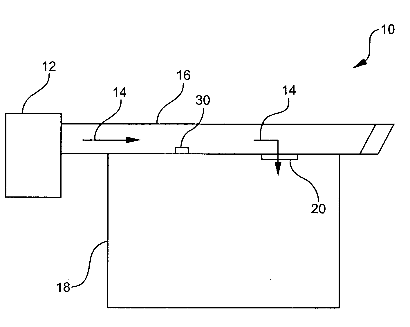
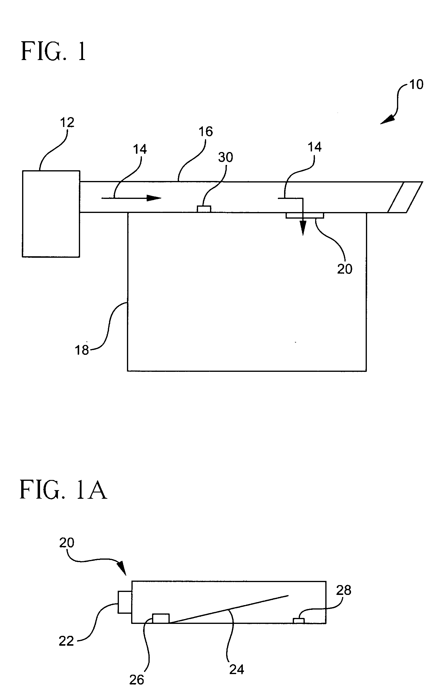
[0027] Referring now to FIG. 1, variable air volume (VAV) system 10 includes a heating, ventilating and air conditioning (HVAC) package 12 for supplying cold or heated supply air 14 (as well as fresh outside air) into a supply air duct 16. A plurality of zones 18 (e.g., an office, conference room, etc.) communicate with supply duct 16 through a plurality of flow control boxes 20 (e.g., pressure independent variable air volume boxes). Typically, each individual zone 18 has at least one flow control box directly associated therewith. VAV system 10 preferably includes a plurality of controllers 22, one controller being associated with each of the individual flow control boxes. However, it is contemplated herein that VAV system 10 can also utilize a single central controller to communicate with all the individual flow control boxes.

[0028] Each of flow control boxes 20 preferably includes a movable damper 24 for regulating flow volume between a selected minimum flow volume (e.g., 333 ft...


PUM


Abstract

A method, as well as a controller, for controlling room temperature within a variable air volume system having a plurality of zones wherein the thermal transfer rate with respect to each of such zones is maintained at a substantially constant value notwithstanding changes in the temperature of the supply air thereby providing improved efficiency and environmental comfort.

Description

[0001] This application is a divisional of copending application Ser. No. 10 / 704,251 filed on Nov. 7, 2003, which claims the benefit of U.S. Provisional Application Ser. No. 60 / 512,495 filed on Oct. 17, 2003.BACKGROUND OF INVENTION [0002] The present invention relates to a variable air volume system and, more particularly, to a variable air volume system having a plurality of zones wherein the thermal transfer rate with respect to each of such zones is controlled for improved efficiency and environmental comfort. [0003] Heating, ventilating and air-conditioning (HVAC) systems are used to both heat and cool the air within an enclosure, e.g., a building or zone within such building. An HVAC system typically includes a heating unit, a cooling unit, a supply air fan, a supply duct for directing air into the enclosure, and a return duct for removing air from the enclosure. It will be appreciated by those skilled in the art that HVAC systems are generally designed to operate in one of thr...

Claims


Application Information

Patent Timeline
Patent Type & Authority Applications(United States)
IPC IPC(8): F24D19/10G05D23/275G01M1/38F24F3/044F24F11/00
CPCF24F3/0442Y02B30/767F24F11/0009F24F11/30F24F11/74F24F11/46F24F11/63
Inventor ATTRIDGE, RUSSELL G. JR.
Owner SIEMENS IND INC
Why Eureka
Try Eureka