Micro electromechanical systems thermal switch

a technology of electromechanical systems and thermal switches, applied in the direction of contacts, semiconductor devices, relays, etc., can solve the problems of thermal switches that cannot be reduced below, switches to premature failure, and limited applicability

Inactive Publication Date: 2006-05-04
HONEYWELL INT INC
View PDF6 Cites 3 Cited by
  • Summary
  • Abstract
  • Description
  • Claims
  • Application Information

AI Technical Summary

Problems solved by technology

These thermal switches include a metal-to-metal contact that results in microwelding, arching, and oxidization that can cause the switch to prematurely fail.
Also, these thermal switches cannot be reduced below a certain size limit and thus, have limited applicability.
Further, these thermal switches include a number of parts that require costly manual construction.
Therefore, these thermal switch set points cannot be adjusted once the switch is fabricated.

Method used


Image

  • Micro electromechanical systems thermal switch
  • Micro electromechanical systems thermal switch
  • Micro electromechanical systems thermal switch

Examples


Embodiment Construction

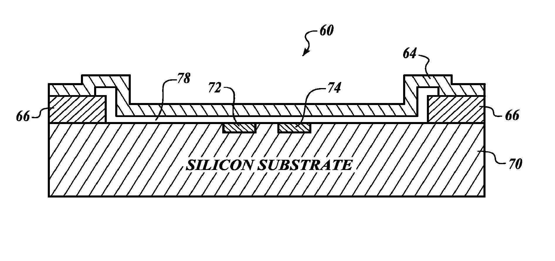
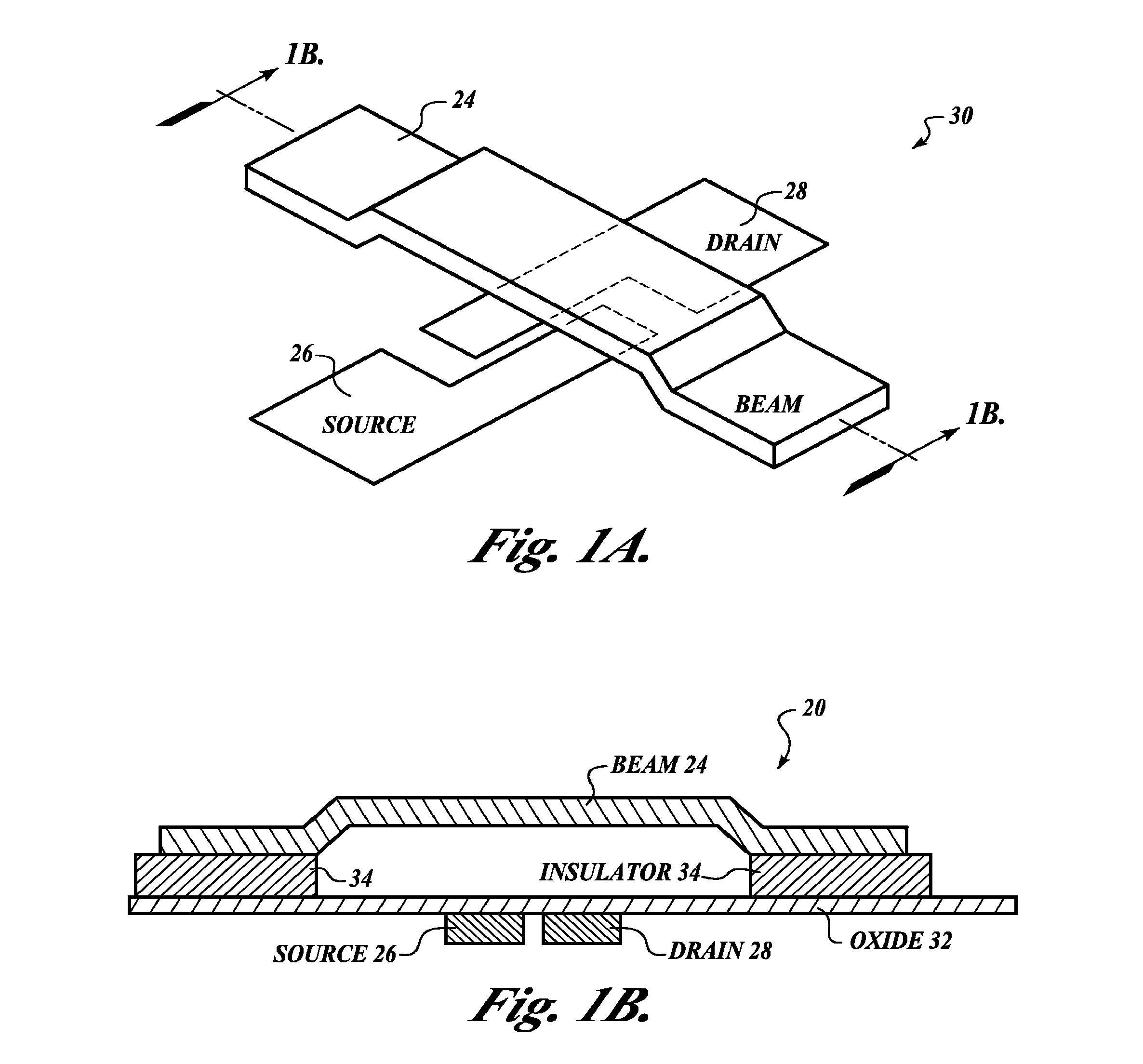
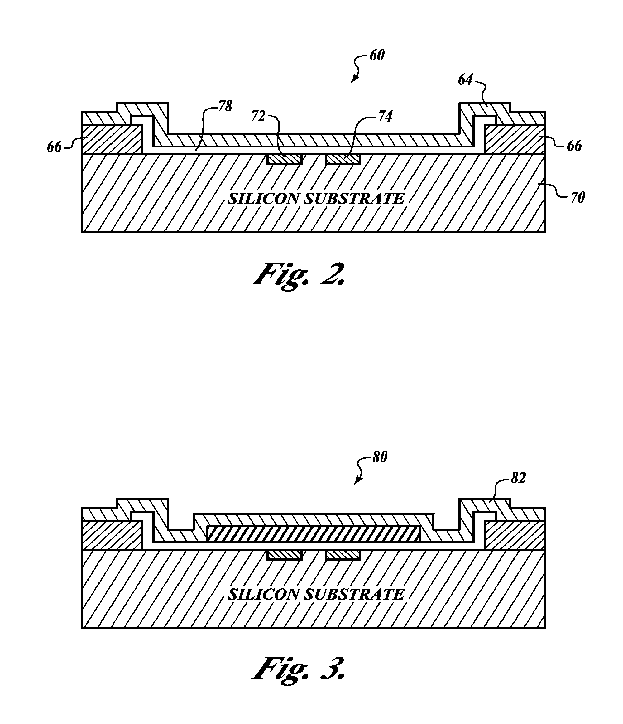
[0015] The present invention is a Micro Electro-Mechanical Systems (MEMS) thermal switch with electrostatic control. FIG. 1A illustrates a perspective view of a single beam MEMS thermal switch 20. The thermal switch 20 includes a beam 24 that is arched over a source 26 and a drain 28 that are created within a silicon substrate 30.

[0016]FIG. 1B illustrates a cross-sectional view of the thermal switch 20 along a longitudinal axis of the beam 24. The source 26 and drain 28 are embedded within silicon substrate 30. The silicon substrate 30 is suitably a silicon wafer. Layered on top of the source 26 and the drain 28 is a gate oxide layer 32. The beam 24 is attached at its ends to insulator mounts 34. The insulator mounts 34 are attached to the gate oxide layer 32 on opposite sides of the source 26 and the drain 28 in order to allow the beam 24 to arch over the source 26 and the drain 28. In one embodiment, the beam 24 includes a monolithic beam. A monolithic beam is a single metal beam...


PUM


Abstract

A Micro Electro-Mechanical Systems (MEMS) thermal switch. The switch includes a FET having a source and drain in a substrate and a beam isolated from the substrate, wherein the beam is a monolithic beam. The beam is positioned over the source and the drain and spaced by a predefined gap. When the thermal set point is reached, the beam moves to electrically connect the source to the drain.

Description

CROSS REFERENCE TO RELATED APPLICATIONS [0001] This application is a continuation in part of a co-pending U.S. patent application Ser. No. 10 / 371,572, filed Feb. 21, 2003, the complete disclosure of which is hereby incorporated by reference.BACKGROUND OF THE INVENTION [0002] Conventional thermal switches use bi or trimetallic disks for performing the switching process. These thermal switches include a metal-to-metal contact that results in microwelding, arching, and oxidization that can cause the switch to prematurely fail. Also, these thermal switches cannot be reduced below a certain size limit and thus, have limited applicability. Further, these thermal switches include a number of parts that require costly manual construction. The set point of these thermal switches is determined by the material and geometry of the thermal disk used and cannot be adjusted after construction. Therefore, these thermal switch set points cannot be adjusted once the switch is fabricated. [0003] There...

Claims


Application Information

Patent Timeline
Patent Type & Authority Applications(United States)
IPC IPC(8): H01L29/84H01H1/00H01H37/52H01H61/00
CPCH01H1/0036H01H37/52H01H61/00H01H2037/008
Inventor KANG, JOON-WON
Owner HONEYWELL INT INC
Why Eureka
Try Eureka