Seal for a Gas Turbine Engine Having Improved Flexibility

Active Publication Date: 2006-05-04
H2 IP UK LTD
View PDF13 Cites 24 Cited by
  • Summary
  • Abstract
  • Description
  • Claims
  • Application Information

AI Technical Summary

Benefits of technology

[0008] The present invention discloses a seal that extends between adjacent slots of a gas turbine engine. The seal comprises an outer sleeve having a first generally planar member including a length, a first end, a second end, a width extending therebetween, and a first thickness. A second generally planar member is positioned on the opposite side of the first generally planar member and has a raised portion. Extending from proximate the first end to proximate the second end and located in between the first and second generally planar members is a plurality of third generally planar members. The plurality of third generally pl

Problems solved by technology

While this seal design has shown improved resistance to wear, the seal has minimal flexibility, due especially to the locations of spot welds 138.
However, this seal requires multiple thin slabs which can be an issue in ensuring the proper number o

Method used


Image

  • Seal for a Gas Turbine Engine Having Improved Flexibility
  • Seal for a Gas Turbine Engine Having Improved Flexibility
  • Seal for a Gas Turbine Engine Having Improved Flexibility

Examples


Embodiment Construction

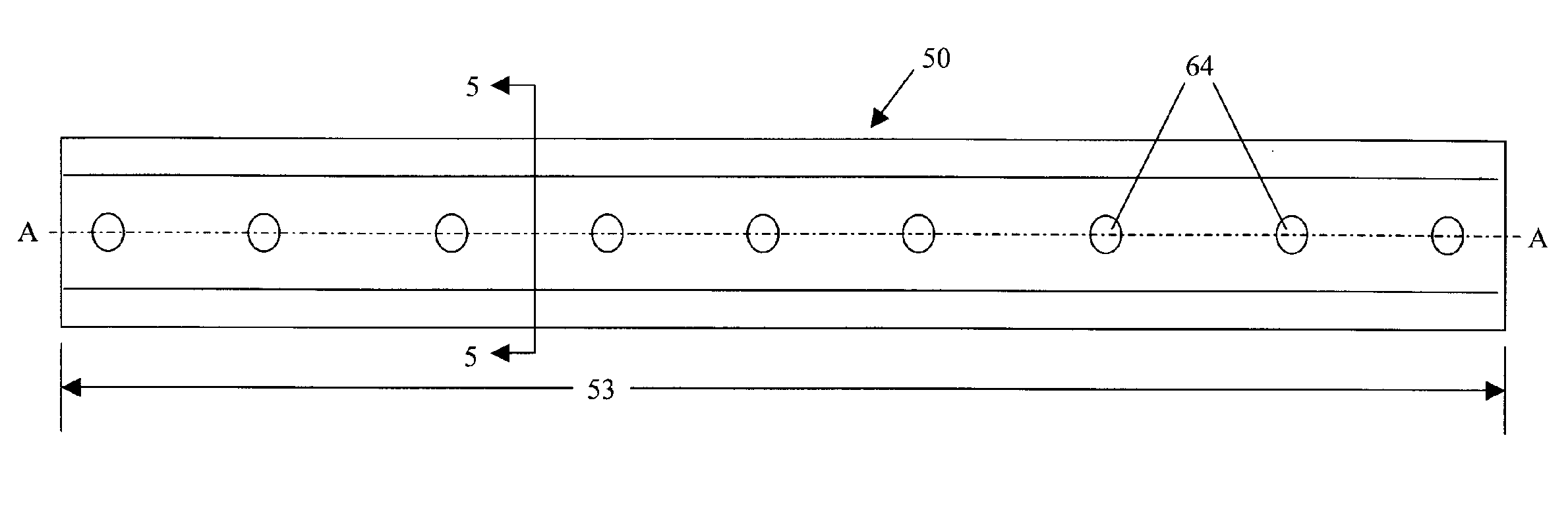
[0016] The preferred embodiment of the present invention is shown in detail in FIGS. 4-6. FIG. 4 depicts an elevation view of seal 50 in accordance with the preferred embodiment of the present invention with FIG. 5 taken as a cross section through the elevation view of FIG. 4. Seal 50 comprises an outer sleeve 51 having a first generally planar member 52 including length 53, first end 54, second end 55, and width 56 extending therebetween. Outer sleeve 52 also has a first thickness 57. Seal 50 further comprises a second generally planar member 58 that is opposite, yet substantially parallel to first generally planar member 51, as is shown in FIG. 5. Second generally planar member 58 has a second thickness 59 and at least one step 60 thereby forming a raised portion 61 of second generally planar member 58.

[0017] Located in between first generally planar member 52 and second generally planar member 58 is a plurality of third generally planar members 62 that each have a third thicknes...


PUM


Abstract

A seal extending between adjacent slots of a gas turbine engine is disclosed. The seal comprises a plurality of generally planar members fixed together along a central axis. The outer member further comprises rounded ends that encompass the second and plurality of third generally planar members. The seal disclosed herein improves sealing capability by providing a more compliant seal over the prior art while reducing the mechanical loads experienced along the seal weld joint, thereby improving seal durability.

Description

[0001] This application hereby claims the benefit of U.S. Provisional Patent Application Ser. No. 60 / 623,515, which was filed Oct. 29, 2004, entitled FLEXIBLE SEAL FOR A GAS TURBINE.TECHNICAL FIELD [0002] The present invention relates generally to a seal and more specifically towards a flexible seal for preventing the leakage of hot gases in a gas turbine engine. BACKGROUND OF THE INVENTION [0003] Gas turbine engines typically comprise a compressor, at least one combustor, and a turbine. The pressure of air passing through the compressor is raised through each stage of the compressor and is then directed towards the combustion system. Gas turbine combustion systems mix fuel with the compressed air and ignite this mixture to create hot combustion gases. The hot combustion gases are then directed towards a turbine, which produces work, typically for thrust, or shaft power if the engine shaft is connected to an electrical generator. [0004] The turbine engine is comprised of numerous in...

Claims


Application Information

Patent Timeline
IPC IPC(8): F16J15/02F16J15/50
CPCF01D11/005F16J15/0887F05D2240/57
Inventor MINNICH, MARK
Owner H2 IP UK LTD
Why Eureka
Try Eureka