
Projection image display apparatus and projection optical unit to be used therein

a technology of projection image and optical unit, which is applied in the direction of instruments, television systems, and television system scanning details, etc., can solve the problems of difficult to achieve thin-sizing apparatus, difficult to achieve widening projection image, and difficulty in widening projection image angle, etc., to reduce trapezoidal distortion and small optical depth of apparatus

Active Publication Date: 2006-05-04
MAXELL HLDG LTD
View PDF3 Cites 25 Cited by
  • Summary
  • Abstract
  • Description
  • Claims
  • Application Information

AI Technical Summary

Benefits of technology

[0010] According to the present invention, an object thereof is to provide a technology for enabling to reduce the distortion of the image on the screen, within an apparatus of projecting the image onto the screen, obliquely or inclined thereto, and thereby obtaining superior characteristics thereof.
[0011] Also, according to the present invention, an object thereof is to provide a technology for enabling to reduce the depth size of the apparatus, and to reduce the distortion of the image on the screen, as well.
[0019] Thus, according to the present invention, it is possible to made the optical depth of the apparatus small, as well as, reducing the trapezoidal distortion caused due to the oblique projection of the image.

Problems solved by technology

However, since the afocal converter has a low magnifying power, therefore it is difficult to widen an angle of the projection image, and for that reason, there is a problem that thin-sizing of the apparatus cannot be achieved.
Also, with the projection optical unit described in the Patent Document 2 mentioned above, from the structure thereof, it is also difficult to obtain widening of the projection image.
Therefore, there is still a problem that sufficient thin-sizing cannot be obtained eve if applying that described in the Patent Document 2 into the rear-surface projection type color image display apparatus.
Furthermore, with the projection optical unit described in the Patent Document 2, it has also other problem that the production thereof is difficult, since the lenses to be used therein must be made eccentric, separately.
For this reason, when producing thereof, it is difficult to maintain accuracy of positioning the respective lenses, sufficiently; therefore, there is a problem that the production thereof is also difficult.

Method used


Image

  • Projection image display apparatus and projection optical unit to be used therein
  • Projection image display apparatus and projection optical unit to be used therein
  • Projection image display apparatus and projection optical unit to be used therein

Examples


embodiment 1

[0069] Referring to FIGS. 5-7 and 12 attached, and further the numerical values shown in Table 1 below, explanation will be made about an embodiment 1. However, in FIG. 5 is shown a schematic diagram of light beams within the present embodiment 1. Thus, the light beam emitted from the image display element, which is disposed in a lower side in the figure, passes through a first optical system 32, which is built up with plural numbers of refraction lenses. Thereafter, it is reflected upon a free shaped surface mirror 33, which builds up a second optical system, and further reflected upon a second free shaped surface mirror 34. Then, it is reflected upon the surface of a rear-surface mirror 35, being a plane mirror, and is incident upon the screen 36.

[0070] Herein, the first optical system mentioned above is a coaxial optical system constructed with refraction surfaces, all of which are coaxial in the configuration. Further, four (4) within those refraction surfaces are constructed w...

embodiment 2

[0088] Next, detailed explanation will be given about a second embodiment of the optical unit, by referring to FIGS. 8-10 and 12, and also Tables 4-6, which will be shown below.

[0089] First of all, FIG. 8 shows the schematic diagram of the light beams within the present embodiment 2. Thus, the light emitting from an image display element 41 passes through a first optical system 42 including plural numbers of lenses therein. Thereafter, it is reflected upon a first free shaped surface mirror 43 within a second optical system, and further upon a second free shaped surface mirror 44. And after being reflected upon a rear-surface mirror 45, being a plane mirror, it is incident upon a screen 46.

[0090] Herein, the first optical system mentioned above is a coaxial optical system constructed with refraction surfaces, all of which are coaxial in the configuration. Further, four (4) within those refraction surfaces are constructed with aspheric surfaces, each being axially symmetric, and ot...


PUM


Abstract

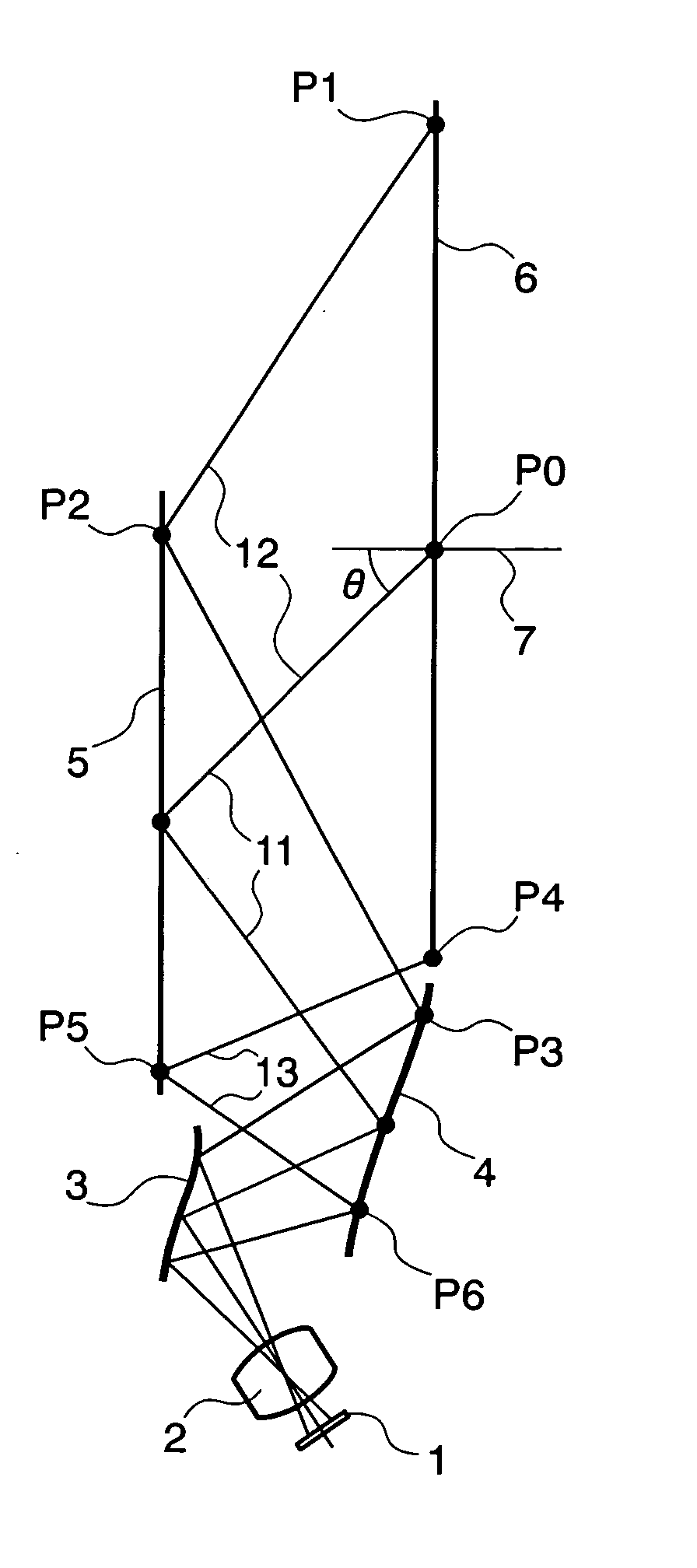
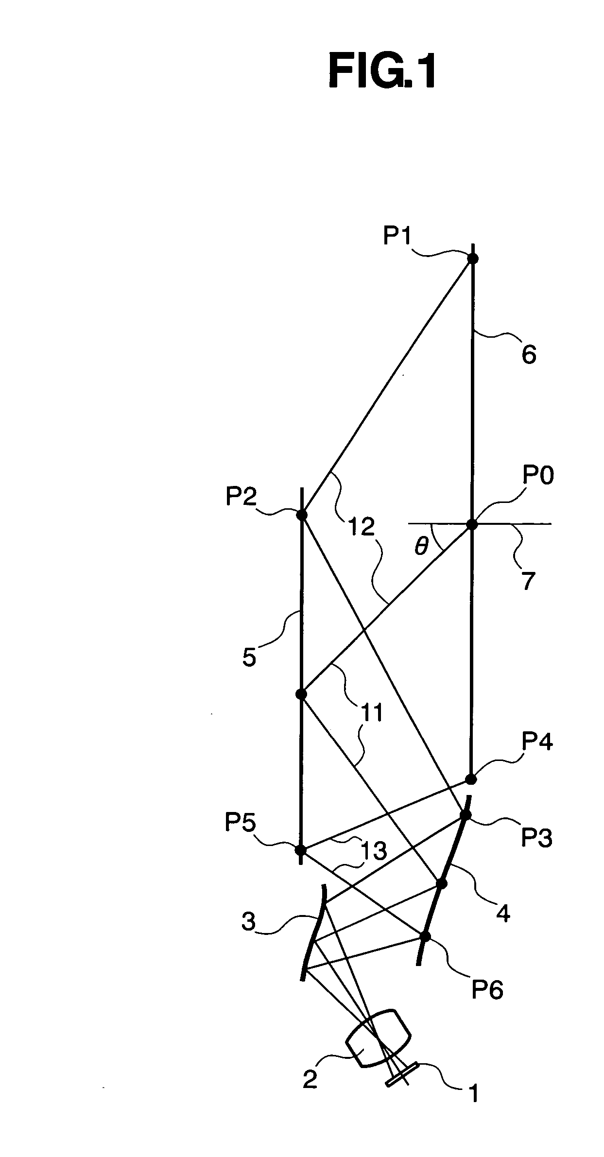
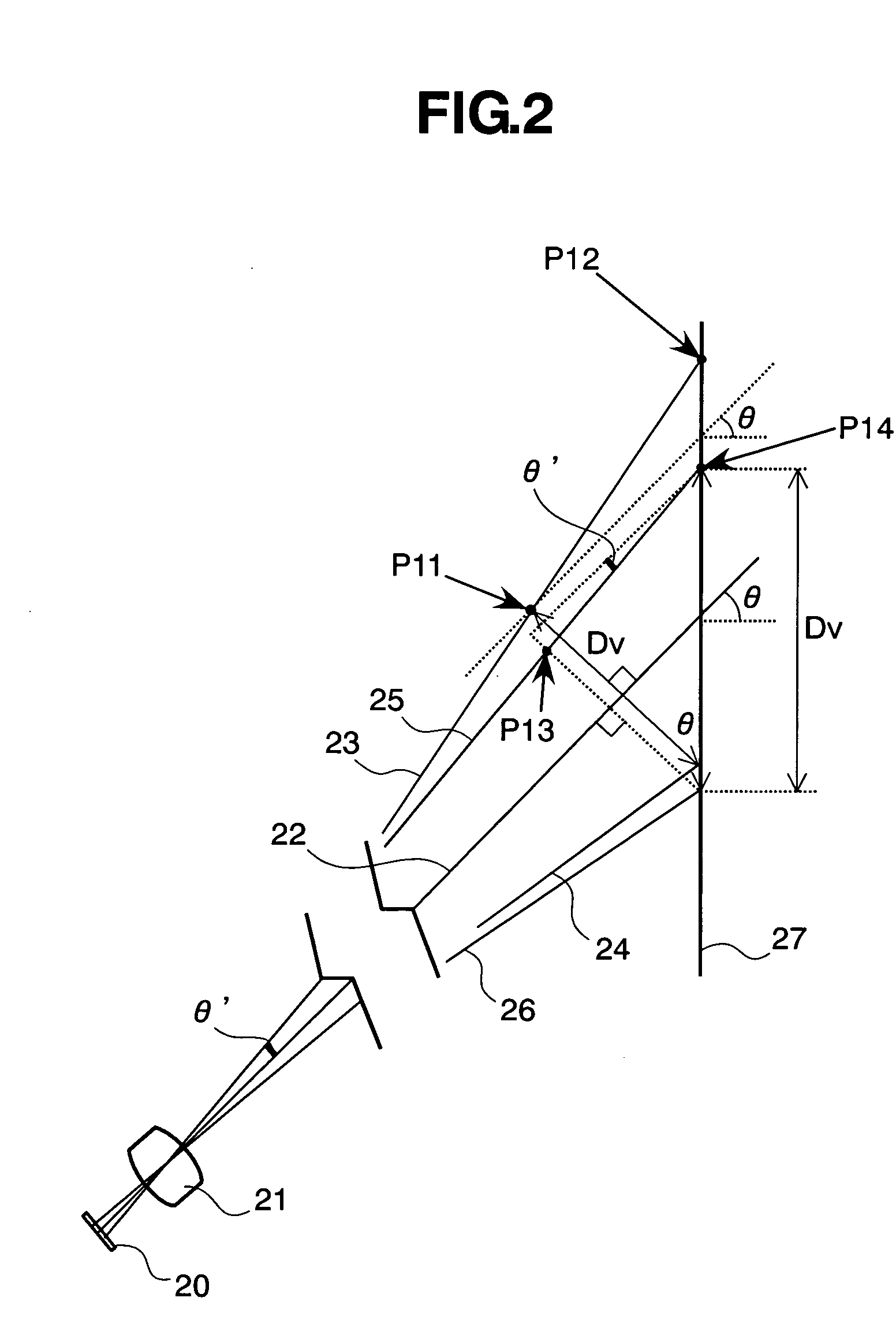
In a projection type image display apparatus, for enlarging an image on a image display apparatus 1 by means of a projection lens 2, thereby projecting the enlarged image onto a screen 6, obliquely, being inclined thereto, between the projection lens 2 and a rear-surface mirror 5, there are disposed free shaped surface mirrors 3 and 4, each having a free shaped surface for compensating a trapezoidal distortion due to oblique projection of the enlarged image. The surface configuration of the free shaped surface mirror is so shaped as to satisfy a following equation: |L1−L2|>1.4·Dv if assuming that a distance for a light beam of an upper end of the enlarged image to reach the screen after being reflected upon a free shaped surface is “L1”, a distance for a light beam of a lower end of the enlarged image to reach the screen after being reflected upon the free shaped surface is “L2”, and a distance from an upper end of an image on the screen to a lower end thereof is “Dv”.

Description

BACKGROUND OF THE INVENTION [0001] 1. Field of the Invention [0002] The present invention relates to a projection image display apparatus for performing an image display through projecting an enlarged image of color onto a screen, for example. And, in particular, the present invention relates to a projection image display apparatus for obtaining the enlarged image on the screen by projecting it obliquely onto the screen, and also a projection optical unit to be used therein. [0003] 2. Description of the Related Art [0004] For so-called a projection-type color image display apparatus, for projecting a color picture on an image display element, such as, a projection-type cathode ray tube (CRT) or a liquid crystal display apparatus (i.e., a liquid crystal panel), etc., for example, enlargedly, on a screen through a projection optical system, requirement is made on reduction in the size, in particular, the depth of the apparatus, as well as, obtaining an enlarged image of sufficient lar...

Claims


Application Information

Patent Timeline
Patent Type & Authority Applications(United States)
IPC IPC(8): G03B21/14
CPCG02B17/0816G03B21/10G03B21/28
Inventor HISADA, TAKANORIYATSU, MASAHIKOHIRATA, KOJI
Owner MAXELL HLDG LTD
Learn More