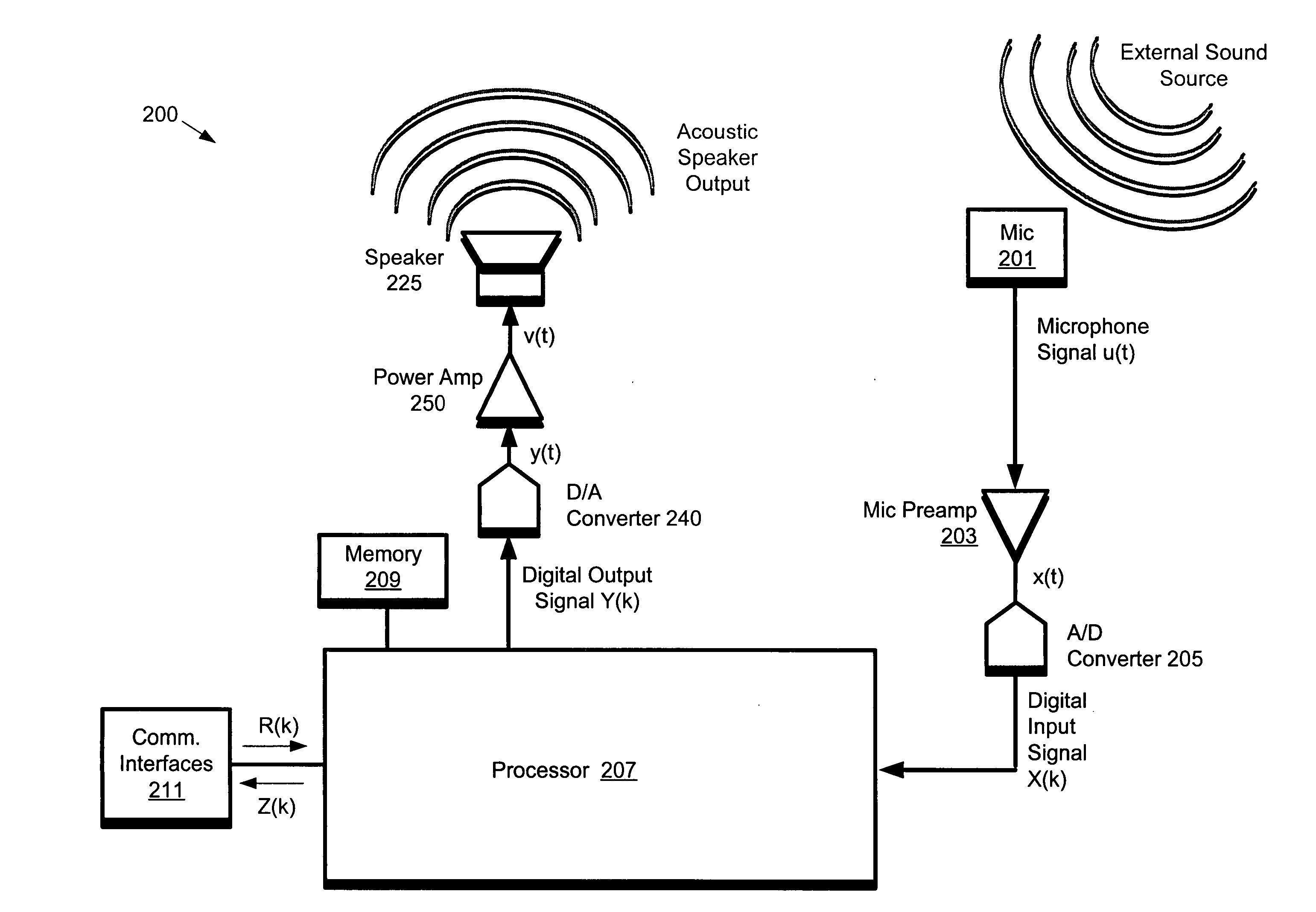
This feedback path may result in uncontrolled oscillation problems.
These methods may require a minimum amount of
settling time.
This may be a problem, especially if sound (e.g., from people and microphones) moves around relative to the
system.
The finite
settling time may also be a problem in multi-channel audio output systems where a signal for each channel is allowed to pan between multiple loudspeakers.
In addition, these AEC algorithms operate with non-zero buffer sizes, which imply a time
delay between when the signal is acquired by the
microphone and when a correction signal may be applied to the speaker output.
If the time
delay is sufficiently long, it may be impossible to control the acoustic echo because the acoustic
delay may be shorter than the overall loop delay in the AEC (e.g., a
control system group delay).
If the buffer size is too small, the
frequency resolution may be too coarse to permit the AEC to operate effectively.
While the
system's sampling rate may be increased in order to increase the number of audio samples available per second, this approach may significantly increase computational overhead.
However, this null may only be effective over a limited frequency range.
In addition, constraining a
loudspeaker directional pattern may have an
adverse effect on the perceived
sound quality for the desired output (i.e., the speaker may sound different depending on the directional angle between the user and the front of the
loudspeaker).
If the microphone
system has a unidirectional response pattern, there may be some angles where the
pickup of external sounds will exhibit different
frequency response characteristics than others, which may provide a non-uniform coloration to the sound
pickup in the so-called “off-axis” directions.
Similarly, a purely pressure-gradient speaker system can suffer from a weak low-
frequency response, depending on the size of the baffle (the surface which separates the front of the speaker driver from the rear).
For speakers, however, it may be more challenging to produce a
transducer that is small in size (for wide dispersion) and able to displace enough air in order to generate an acceptable acoustic output.
While omnidirectional patterns for speakers and microphones may be desirable, such patterns may be challenging in a speaker / microphone
coupling, since this configuration is the one which presents the largest closed-
loop gain in an otherwise uncorrected microphone-speaker system.
Thus, the AEC
algorithm performance (the amount of closed-
loop gain that it can effectively cancel) can suffer if the speaker system produces a highly non-linear output from a given input.
Since speaker systems are more linear at lower excursions (volume levels), this can limit the maximum output level that the speaker can produce without incurring unwanted feedback.
Another problem that can be associated with a closely coupled microphone-speaker system is that the speaker is typically much closer to the microphone (in the sense of spatial distance) than the
sound sources (conference participants) present in the outside room.
However, in that case, the high
gain of the system may cause unwanted overloading of the
microphone preamplifier stage due to the excessively strong response in this microphone system from the output of the speaker system.
For example, power cords to the
speakerphone may be cumbersome.
In addition, batteries may be expensive and short lived which could cause problems in long conference calls.


