Generator set exhaust processing system and method

a technology of exhaust processing and generator sets, applied in the direction of vessel auxillary drives, marine propulsion, vessel construction, etc., can solve the problems of variable components, inapplicability of devices to smaller watercraft, and watercraft employing exhaust processing devices in conjunction, so as to reduce undesirable components of exhaus

Inactive Publication Date: 2006-05-04
KOHLER CO
View PDF15 Cites 7 Cited by
  • Summary
  • Abstract
  • Description
  • Claims
  • Application Information

AI Technical Summary

Benefits of technology

[0008] The present invention overcomes the aforementioned drawbacks by providing a system and method for processing exhaust produced by a watercraft genset to reduce undesirable components of the exhaust before the exhaust is expelled from the watercraft. Furthermore, a system and method protects the exhaust-processing system from presenting external surfaces with undesirable temperatures.

Problems solved by technology

This exhaust, if unprocessed, has various components that are undesirable for a number of reasons, such as potentially pollutive elements and undesirable smells.
Despite these undesirable characteristics of exhaust, relatively few watercraft employ any exhaust-processing devices in conjunction with onboard gensets to eliminate or reduce the undesirable exhaust components from the exhaust being expelled into the environment.
In fact, with the exception of watercraft employing gensets having high-power ratings (e.g., above 25 hp), conventional watercraft are not mandated by current Environmental Protection Agency (EPA) requirements to employ any exhaust-processing devices.
Further, while some watercraft (particularly larger watercraft that employ high-power gensets) employ exhaust-processing devices, these devices are not readily applicable to smaller watercraft, particularly pleasurecraft because they add to the size and cost of the genset and present a relatively hot surface that cannot be adequately arranged within the confined spaces of smaller watercraft.
In smaller watercraft, however, due to the relatively cramped quarters on the craft, it is difficult to arrange a genset and an associated exhaust-processing system so that people will not brush up against, or otherwise come into contact with, the heated surfaces of the system.

Method used


Image

  • Generator set exhaust processing system and method
  • Generator set exhaust processing system and method
  • Generator set exhaust processing system and method

Examples


Embodiment Construction

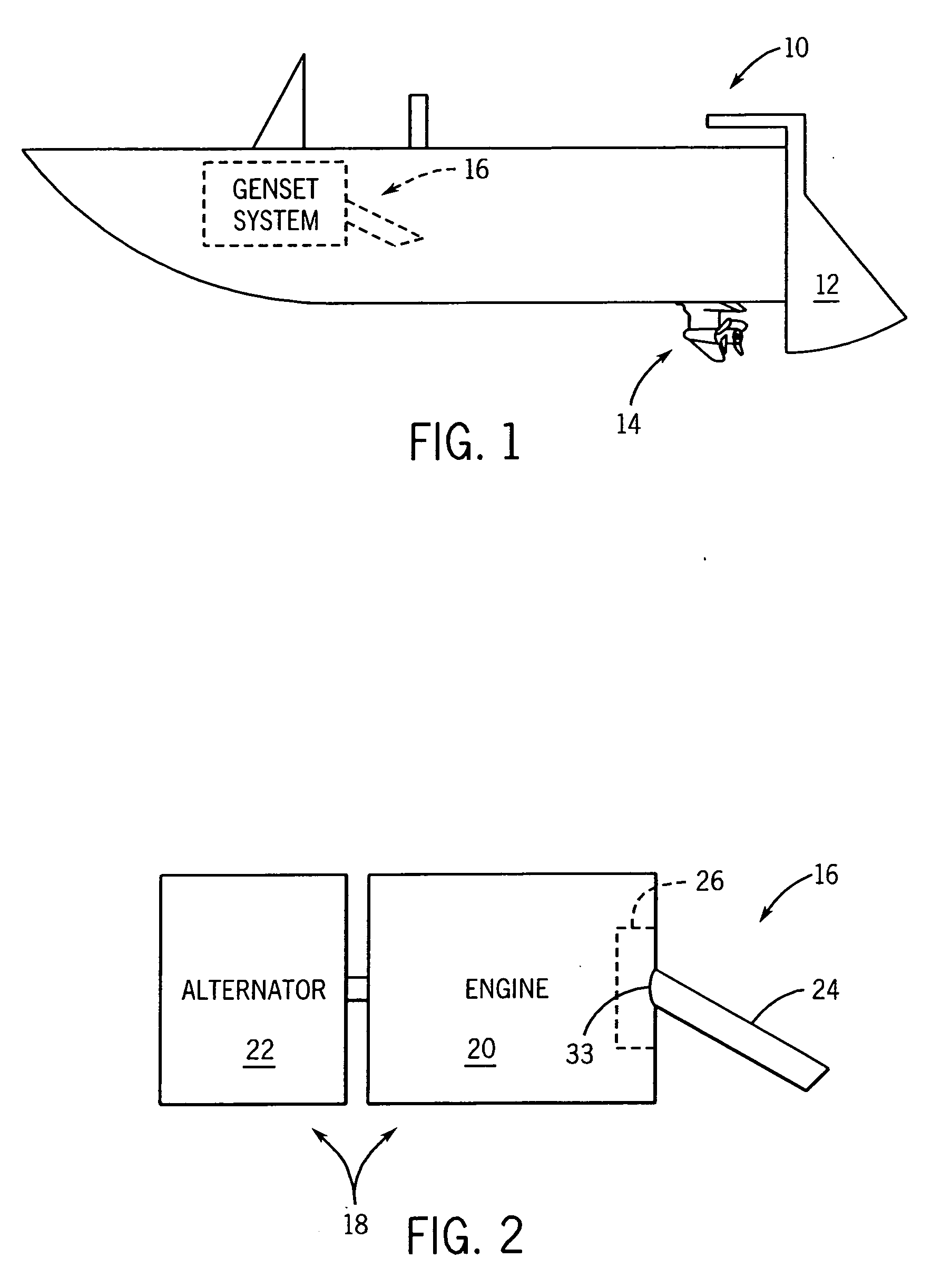
[0018] Referring to FIG. 1, a small watercraft 10 is represented as a speedboat. The watercraft includes, among other components, a rudder 12 and a propeller 14 that is driven to propel the boat through the water. Additionally, as will be described, the watercraft 10 includes a generator set (or “genset”) system 16. The watercraft 10 could be, for example, a pleasure craft having a length in the range of 26 feet to 38 feet. Although shown to be a speedboat, the watercraft 10 is intended to be representative of a wide variety of different watercraft including, for example, sport boats, cruisers, sailboats, yachts, fishing boats, jet boats, and the like that employ gensets. In this regard, the present invention is intended to be applicable to a wide variety of smaller watercraft or other devices that employ gensets and that are able to draw upon a source of water.

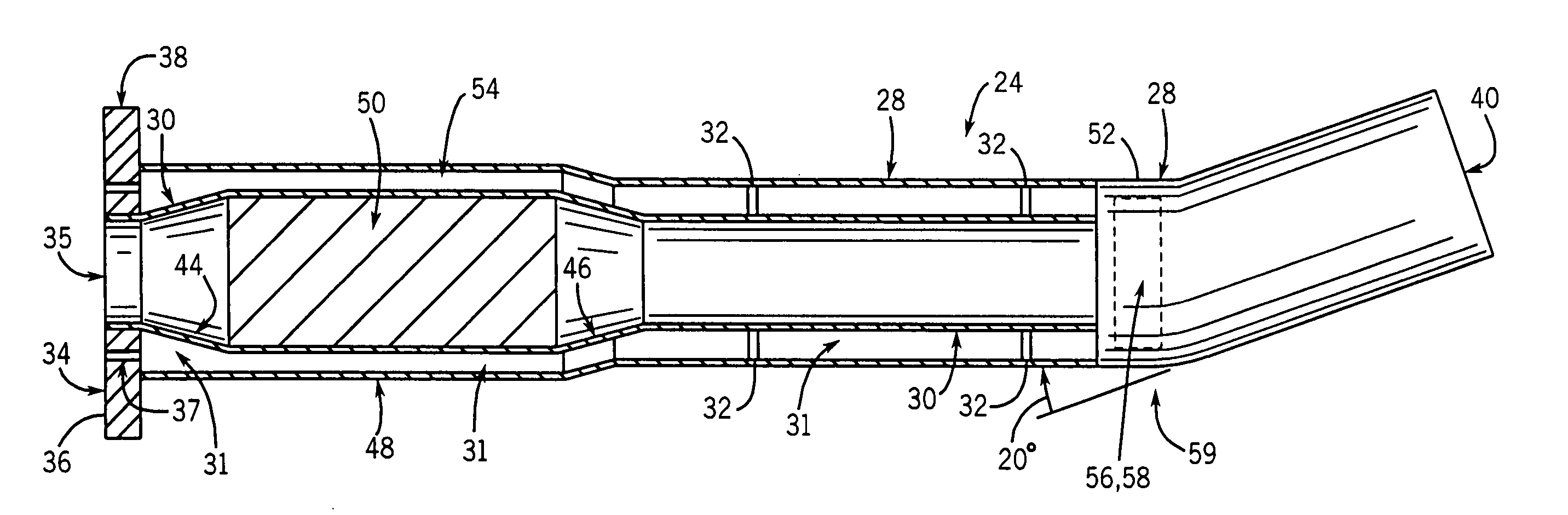
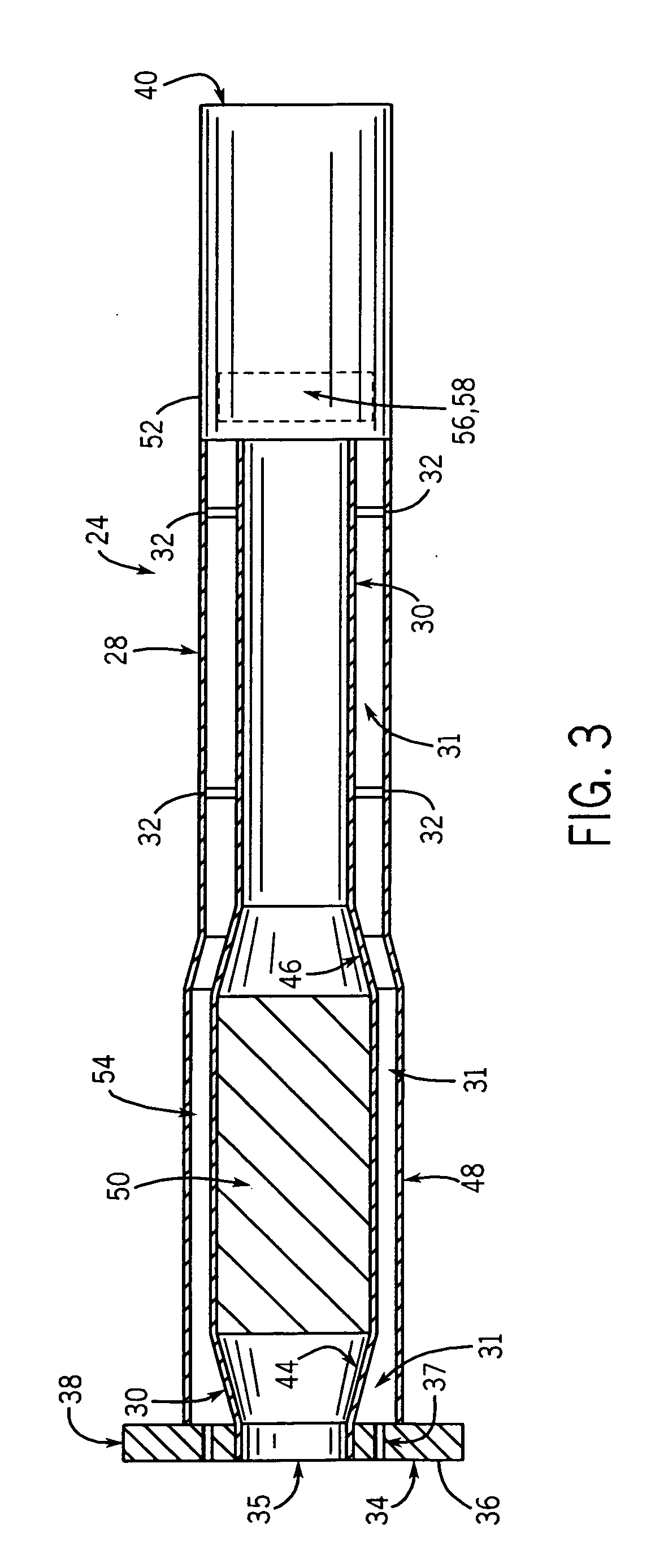
[0019] Referring additionally to FIG. 2, the genset system 16 is shown in detail. The generator set assembly 16 includes a...


PUM


Abstract

An exhaust processing device for implementation in a marine environment is disclosed. The exhaust processing device includes an inner tubular structure configured to receive exhaust gases from a generator set (genset) and communicate the exhaust gases therethrough. The exhaust processing device also includes an exhaust processing element mounted within the inner tubular structure to process the exhaust gases and an outer tubular structure mounted around the inner tubular structure to form an intermediate space therebetween. The exhaust processing device further includes at least one orifice through which to deliver a flow of water to the intermediate space to maintain the outer tubular structure at a temperature below a temperature of the exhaust processing element.

Description

CROSS REFERENCE TO RELATED APPLICATIONS [0001] This application claims the benefit of U.S. Provisional Application 60 / 621,134 filed Oct. 22, 2004, entitled “Exhaust Processing Assembly for Marine Application”.STATEMENT REGARDING FEDERALLY SPONSORED RESEARCH OR DEVELOPMENT [0002] Not applicable. FIELD OF THE INVENTION [0003] The present invention relates generally to generator sets and, more particularly, to an exhaust possessing system for generator sets employed within watercraft such as pleasure boats. BACKGROUND OF THE INVENTION [0004] Watercraft such as sport boats, cruisers, sailboats, yachts, fishing boats, jet boats, and the like, commonly employ on-board generator sets (often referred to as “gensets”) to generate electricity for use on the watercraft. The gensets typically include an alternator driven by a dedicated internal combustion engine. As with all internal combustion engines, the engines of gensets produce exhaust. This exhaust, if unprocessed, has various components...

Claims


Application Information

Patent Timeline
Patent Type & Authority Applications(United States)
IPC IPC(8): B63H21/34B63H21/32B63H21/38F01N3/28F01N7/00F01N3/04F01N13/00F01N13/14
CPCB63B2770/00B63H21/32B63J3/04F01N3/043F01N3/28F01N13/004F01N13/14F01N13/141F01N2260/024F01N2590/02F01P2050/02F01P2060/10F02M31/20Y02T10/20F01N13/009Y02T10/12
Inventor ZWIEG, BRIAN MATTHEWKOEHL, RICHARD R.
Owner KOHLER CO
Why Eureka
Try Eureka