Integrated exhaust gas after-treatment system for diesel fuel engines

an exhaust gas aftertreatment and diesel fuel technology, which is applied in the direction of engines, machines/engines, mechanical apparatus, etc., can solve the problems that none of the exhaust aftertreatment systems known in the prior art is directed towards eliminating different pollutants, and achieve the effect of reducing undesirable components

Active Publication Date: 2015-02-10
MAHINDRA & MAHINDRA LTD
View PDF11 Cites 2 Cited by
  • Summary
  • Abstract
  • Description
  • Claims
  • Application Information

AI Technical Summary

Benefits of technology

[0007]An object of the present invention is to integrate various elements of an exhaust gas treatment system to reduce undesirable components from an exhaust gas emitted from an engine of a vehicle, thereby enabling the vehicle to meet stringent emission norms.
[0010]Another object of the present invention is to integrate the various elements of the exhaust gas after-treatment system on a compact vehicle such as a small truck, a small utility vehicle (SUV) or a car with a monocoque construction or body over chassis design, thereby facilitating easy access to the various components of the exhaust gas after-treatment system, such as a reducing agent filing system.
[0011]Still another object of the present invention is to provide an exhaust gas after system fitted with a particulate filter that may be periodically regenerated without even requiring intervention of the user, wherein a DELTA PRESURE sensor, a NOX sensor works in conjunction with an engine control unit (ECU) for controlling engine parameters that in turn facilitate in achieving regeneration of the particulate filter and thereby improve the optimum performance of the engine.
[0024]Further, the integrated exhaust gas after-treatment system includes a pair of pressure sensors, wherein a first pressure sensor of the pair of pressure sensors is disposed upstream of the Diesel Particulate Filter (DPF) and a second pressure sensor of the pair of pressure sensors is disposed downstream of the Diesel Particulate Filter (DPF) for determining pressure drop across the Diesel Particulate Filter (DPF), thereby facilitating in determining level of blockage of the Diesel Particulate Filter (DPF) by particulate matter trapped therein.
[0027]Further, the integrated exhaust gas after-treatment system includes a mixer assembly disposed downstream of the dosing module and upstream of the Selective Catalytic Reduction (SCR) for facilitating homogeneous mixing of the reducing agent injected by the dosing module with the exhaust gases leaving the Diesel Oxidation Catalyst (DOC)-Diesel Particulate Filter (DPF) assembly.

Problems solved by technology

However, none of the exhaust after treatment systems known in the prior art are directed towards eliminating different pollutants, i.e. CO, NO, hydrocarbons, NOx emissions, particulate matter present in the exhaust gases emitted from a diesel fuel engine collectively, irrespective of the nature of the pollutant.

Method used


Image

  • Integrated exhaust gas after-treatment system for diesel fuel engines
  • Integrated exhaust gas after-treatment system for diesel fuel engines
  • Integrated exhaust gas after-treatment system for diesel fuel engines

Examples


Embodiment Construction

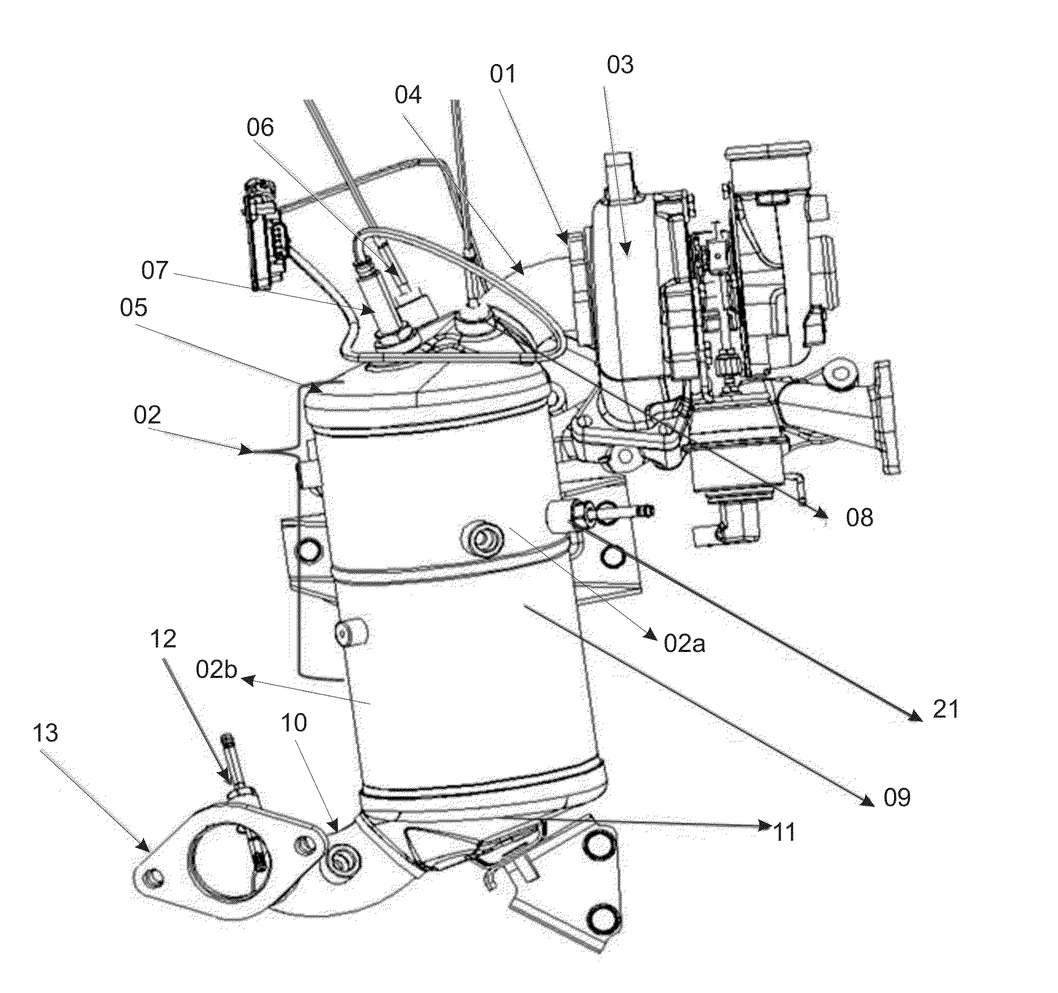
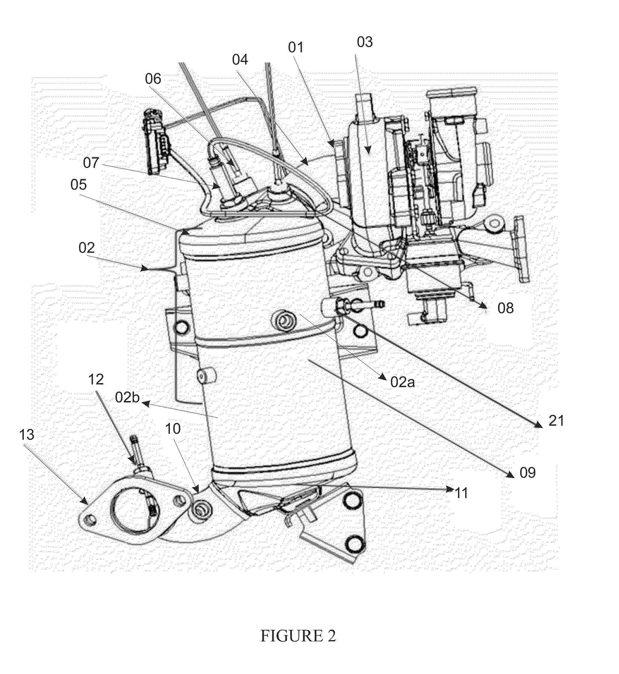
[0040]The present invention discloses an integrated layout of an exhaust gas after treatment system used for purification of exhaust gases emitted from an exhaust manifold of a diesel engine. However, with certain adaptations the integrated layout of an exhaust gas after treatment system may also be applicable to gasoline or Compressed Natural Gas (CNG) and Liquid Petroleum Gas (LPG) engines.

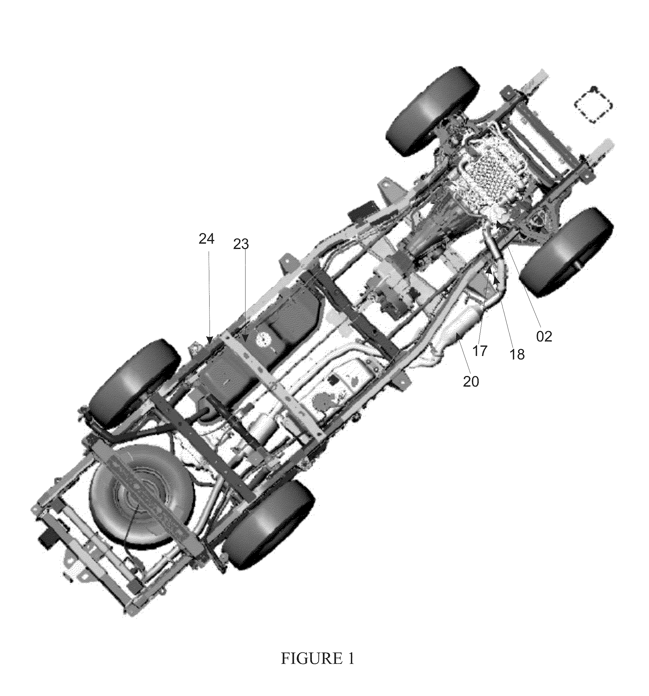
[0041]In accordance with the system-layout of the present invention, a turbocharged diesel engine is connected to an exhaust after treatment passage. The turbocharger of the engine is connected with the exhaust after treatment passage by means of a flange. The exhaust after treatment passage includes a replaceable Diesel Oxidation Catalyst (DOC) and a Diesel Particulate Filter (DPF) assembly as separate modules. An upstream cone of the DOC-DPF assembly is designed to achieve optimum possible uniformity index for the velocity of the gas at the entrance of the DOC-DPF assembly. Generally the unifo...


PUM


Abstract

An integrated exhaust gas after-treatment system for eliminating pollutants present in exhaust gases is disclosed. The integrated exhaust gas after-treatment system includes a Diesel Oxidation Catalyst (DOC)-Diesel Particulate Filter (DPF) assembly, a Selective Catalytic Reduction (SCR), a dosing module and a reducing agent supply system. The Diesel Oxidation Catalyst (DOC)-Diesel Particulate Filter (DPF) assembly is connected to an exhaust gas manifold of an engine and includes a canister for holding a Diesel Oxidation Catalyst (DOC) and a Diesel Particulate Filter (DPF). The Diesel Particulate Filter (DPF) is disposed downstream of the Diesel Oxidation Catalyst (DOC) and is spaced there-from. The Selective Catalytic Reduction (SCR) is disposed downstream of the Diesel Oxidation Catalyst (DOC)-Diesel Particulate Filter (DPF) assembly and facilitates elimination of NOx present in the exhaust gases by reduction of the NOx.

Description

CROSS-REFERENCE TO RELATED APPLICATIONS[0001]This application claims the priority, under 35 U.S.C. §§119, 120, 363, and 371, of India patent application No. 3490 / MUM / 2010, filed Dec. 22, 2010, and International Application No. PCT / 1N2011 / 000859, filed Dec. 15, 2011, which designated the United States and was published in English; the prior applications are herewith incorporated by reference in their entirety.STATEMENT REGARDING FEDERALLY SPONSORED RESEARCH OR DEVELOPMENT[0002]Not Applicable.FIELD OF THE INVENTIONBackground[0003]Generally, exhaust gases emitted from an exhaust manifold of an engine are led to a catalytic converter mounted in an exhaust gas passage disposed down-stream of the exhaust manifold. The exhaust gases contain hydrocarbons, carbon monoxide and oxides of nitrogen, some portions of which are oxidized in the vicinity of noble earth metals. The exhaust gases further includes particulate matter in the form of soot that is required to be eliminated by a particulate...

Claims


Application Information

Patent Timeline
Patent Type & Authority Patents(United States)
IPC IPC(8): F01N3/00F01N3/021F01N3/10F01N3/20F01N13/02
CPCF01N3/021F01N3/103F01N3/2066F01N13/02F01N2560/06Y02T10/24F01N2560/025F01N2560/026F01N2560/08F01N2610/02Y02A50/20Y02T10/12
Inventor PATADE, VISHNU KEDARIKOKATE, RAKESH JANARDHANHARDIKAR, MADHAV ANANTVELUSAMY, RAMASAMY
Owner MAHINDRA & MAHINDRA LTD
Why Eureka
Try Eureka