
Digital video signal transmission apparatus and image display apparatus

a digital video and image display technology, applied in the field of digital video signal transmission apparatus, can solve the problems of reducing requiring a larger substrate or circuit size, and generating undesirable radiation noise, so as to reduce the data amount of the digital video signal, reduce the undesirable, and reduce the power consumption of the system

Inactive Publication Date: 2006-05-09
SHARP KK
View PDF9 Cites 2 Cited by
  • Summary
  • Abstract
  • Description
  • Claims
  • Application Information

AI Technical Summary

Benefits of technology

[0009]The present invention is contrived in order to solve the forgoing conventional problems, and has an object to provide a digital video signal transmission apparatus that can reduce a data amount of a digital video signal, which is transmitted via data transmission path, and especially to provide a digital video signal transmission apparatus that can carry out the parallel transmission, in which the digital video signal is divided per bit among a plurality of the data transmission lines and transmitted per bit via the transmission lines, without requiring a larger substrate or a greater circuit size, while cutting the power consumption of the system (the image display apparatus) and reducing the undesirable radiation noise, and to provide an image display apparatus incorporated with same.

Problems solved by technology

Such a problem is posed that this may demand a larger substrate or bigger circuit size.
Another problem is that the increase in the number of the data transmission lines causes a greater consumption of power in a system (an image display apparatus) which is incorporated with a transmission apparatus and a reception apparatus, while increasing undesirable radiation noise generated by the data transmission lines.

Method used


Image

  • Digital video signal transmission apparatus and image display apparatus
  • Digital video signal transmission apparatus and image display apparatus
  • Digital video signal transmission apparatus and image display apparatus

Examples


Embodiment Construction

[0032]Described below is an embodiment of the present invention, referring to FIGS. 1 through 7.

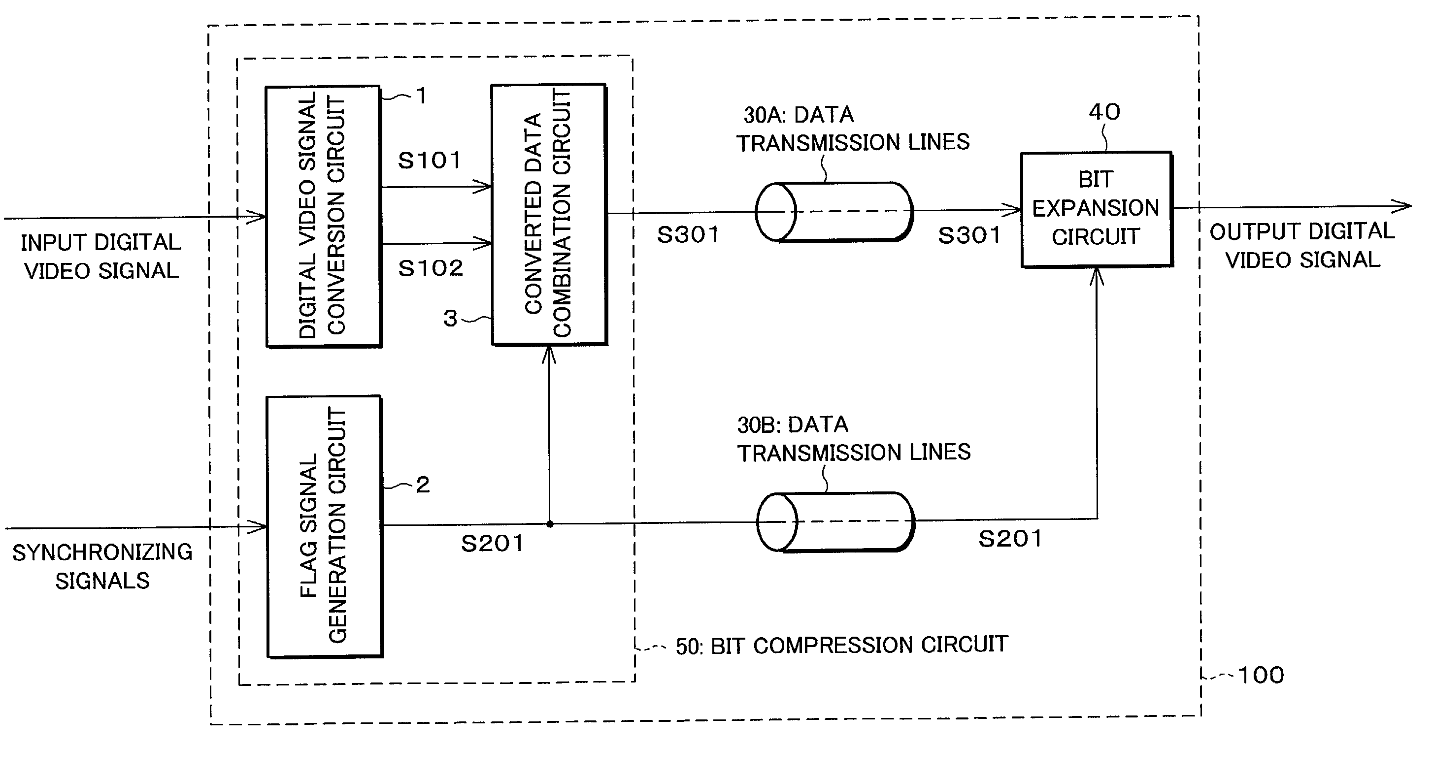
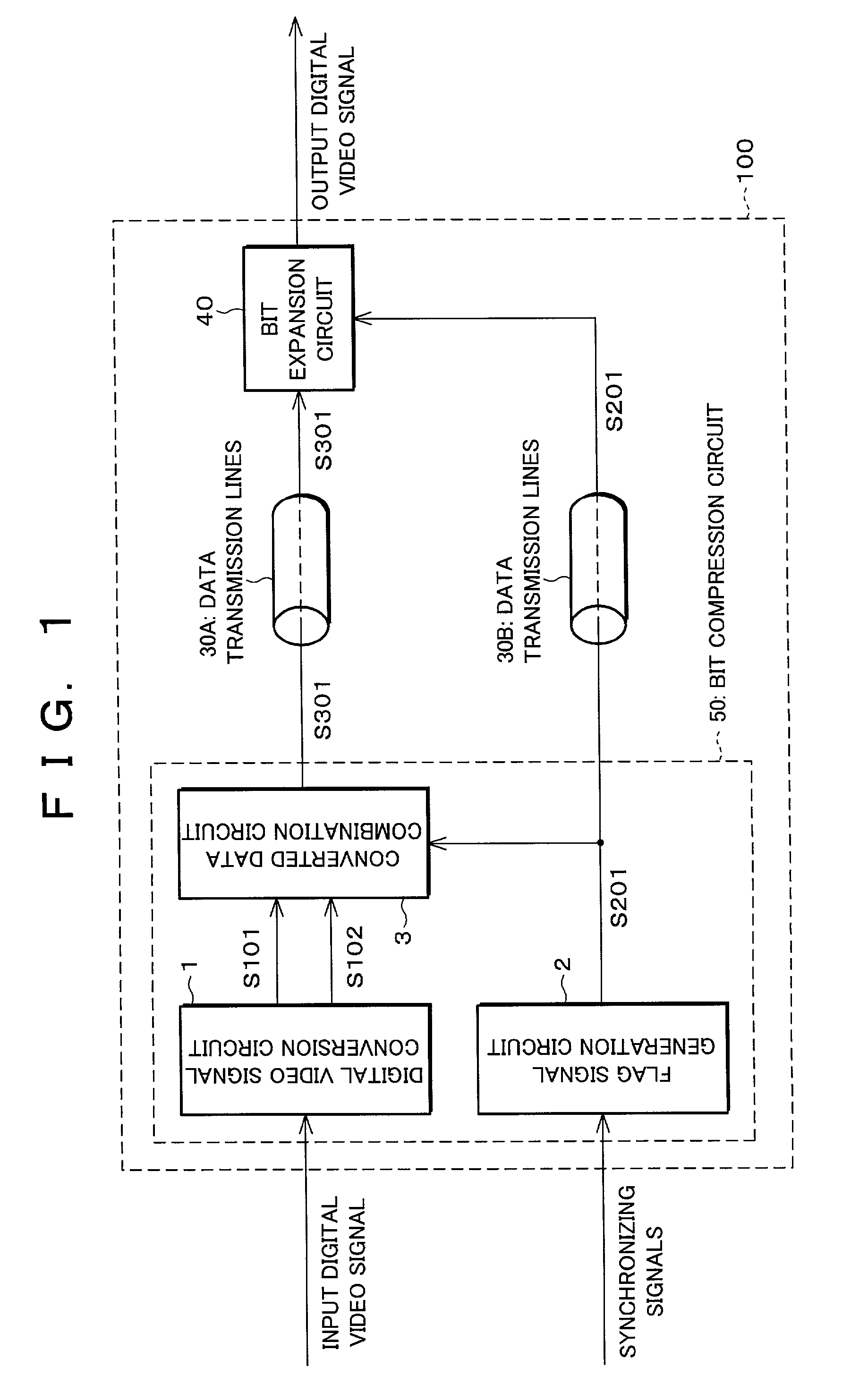
[0033]FIG. 1 shows a schematic block diagram illustrating a digital video signal transmission apparatus of the embodiment of the present invention.

[0034]As shown in FIG. 1, a digital video signal transmission apparatus 100 of the present embodiment is provided with a bit compression circuit (digital video signal compression apparatus) 50, a plurality of data transmission lines (data transmission path) 30A, and a bit expansion circuit (bit expansion means) 40. The bit compression circuit 50 carries out bit compression of an input digital video signal. The data transmission lines 30A transmit, as transmission data S301, the digital video signal, which has been subjected to bit compression. The bit expansion circuit 40 performs bit expansion of the transmission data S301, which has been transmitted. Moreover, the bit compression circuit 50 is provided with a digital video signal conversion c...


PUM


Abstract

A digital video signal transmission apparatus is provided with (a) a digital video signal conversion circuit for converting each chrominance signal of an input digital video signal in such a manner that every plural frames (1) in one frame of the plural frames each chrominance signal is converted into a signal having plural bits, (2) in the other frames of the plural frames, each chrominance signal is converted into a signal having 1 bit, so that an average of gradation levels of the respective chrominance signals in plural frames after the conversion is substantially equal to gradation levels of the respective chrominance signals in a single frame before conversion, (b) a flag signal generation circuit for generating a flag signal for setting the respective chrominance signals in each pixel signal, so that one of the chrominance signal has plural bits, while the other chrominance signal has one bit, (c) a converted data combination circuit for assigning each signal to each of the chrominance signal in accordance with the flag signal, and (d) a bit expansion circuit for carrying out bit expansion of the digital video signal in accordance with the flag signal, so that each chrominance signal has an identical number of bits in each pixel signal. This provides an image display apparatus that can reduce a data amount of the digital video signal which is transmitted via a data transmission path.

Description

FIELD OF THE INVENTION[0001]The present invention relates to a digital video signal transmission apparatus that transmits, through a data transmission path, a digital video signal in which a plurality of chrominance signals having plural bits per pixel are combined. Particular, the present invention relates to a digital video signal transmission apparatus, which carries out bit compression (data compression) of a digital video signal, so as to use fewer data transmission lines that are necessary for parallel transmission in which a pixel signal (a signal, which expresses information on each pixel, and has plural bits) is divided per bit among a plurality of data transmission lines and transmitted via the data transmission lines per bit. Further, the present invention relate to an image display apparatus incorporated with same. Furthermore, the present invention also relates to a digital video signal compression apparatus and a method of compressing a digital video signal for reducin...

Claims


Application Information

Patent Timeline
Patent Type & Authority Patents(United States)
IPC IPC(8): H04N7/12G09G5/00H04N11/02H03M7/30H04N11/04H04N19/00H04N19/13H04N19/134H04N19/182H04N19/184H04N19/196H04N19/42H04N19/46H04N19/70H04N19/94
CPCH04N11/042H04N19/59H04N19/184H04N19/186H04N7/12
Inventor YASUNISHI, NORIOSATOH, FUTOSHI
Owner SHARP KK
Learn More