Chain tensioner

Inactive Publication Date: 2006-05-04
NTN CORP
View PDF7 Cites 27 Cited by
  • Summary
  • Abstract
  • Description
  • Claims
  • Application Information

AI Technical Summary

Benefits of technology

[0027] This minimizes the wear of the sliding surfaces of the cylind

Problems solved by technology

However, because a hydraulic pump for supplying hydraulic oil into the damper chamber through the oil supply passage has just been started, it cannot fill the damper chamber, of which the volume is quickly increasing, with oil at a sufficient speed.
This may cause the inclusion of air in the damper chamber.
Air in the damper chamber will greatly deteriorate the function of the chain tensioner as a dam

Method used


Image

  • Chain tensioner
  • Chain tensioner
  • Chain tensioner

Examples


Embodiment Construction

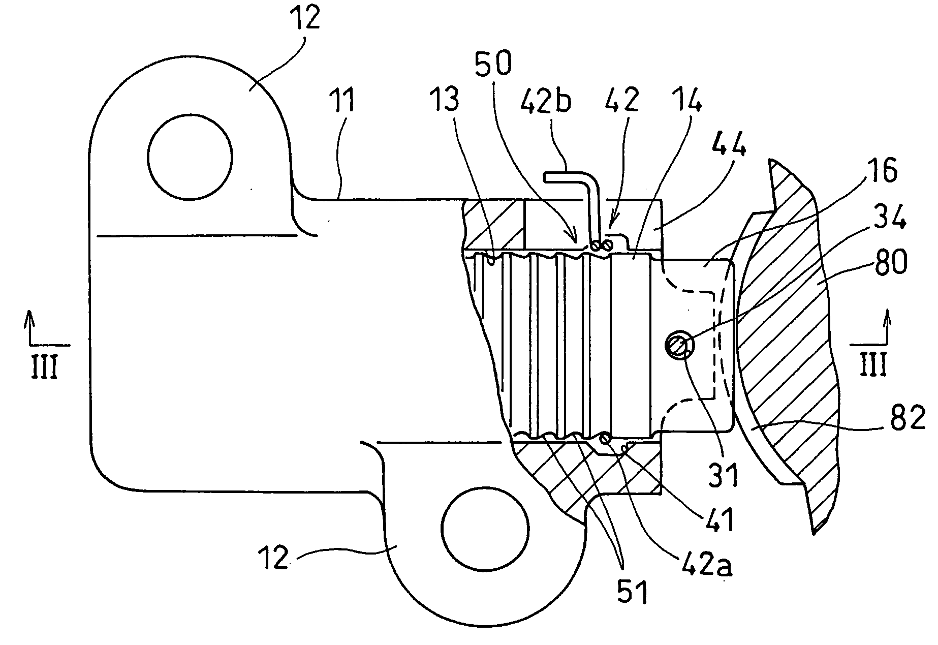
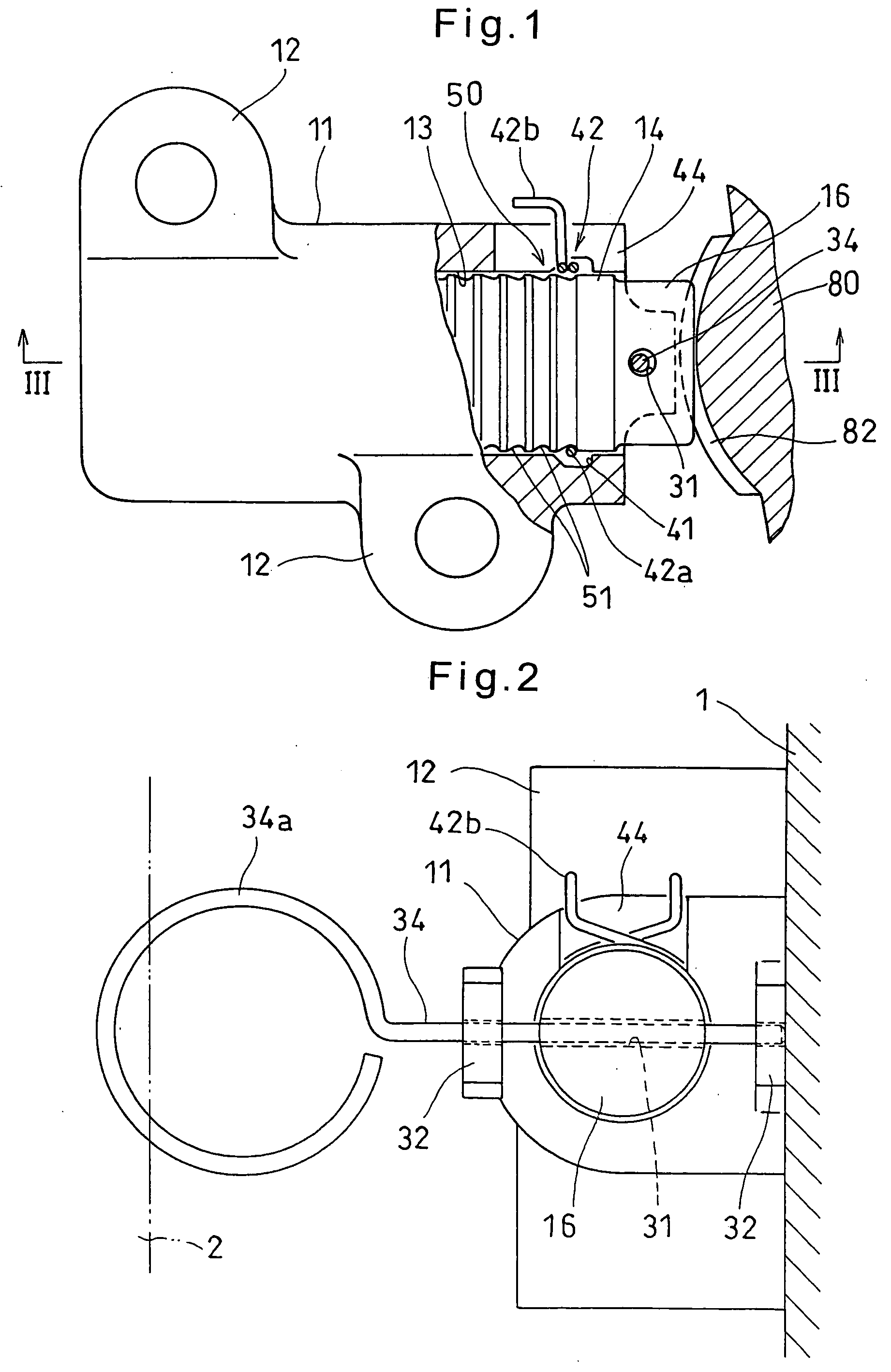
[0042] Now referring to the drawings, the chain tensioner shown in FIG. 1 includes a housing 11 having a plurality of mounting pieces 12 which are bolted to an engine block 1.

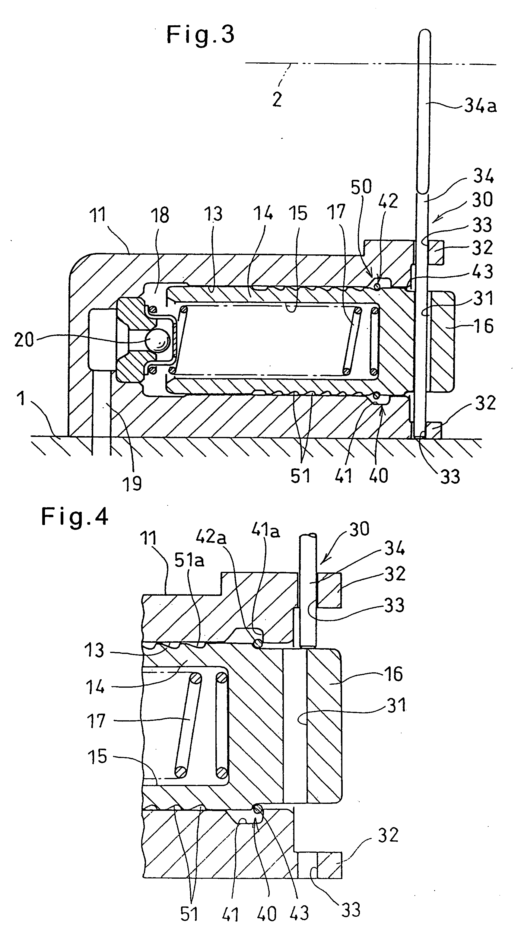
[0043] As shown in FIG. 3, the housing 11 defines a cylinder chamber 13 having an opening at one end of the housing 11. A plunger 14 is slidably mounted in the cylinder chamber 13.

[0044] The plunger 14 is formed with a bore 15 having an opening at the rear end of the plunger 14, and includes a small-diameter portion 16 at its front end. The small-diameter portion 16 is received in the guide groove 82 formed in the plunger abutment of the chain guide 80 shown in FIG. 11 to prevent the chain guide 80 from moving laterally (transverse to the guide groove 82). Since the chain guide 80 is shown in FIG. 11, only its plunger abutment is shown in FIG. 1. A spring 17 is mounted between the closed end of the bore 15 and the closed end of the cylinder chamber 13 to bias the plunger 14 out of the cylinder chamber 13.

[00...


PUM


Abstract

A chain tensioner includes a housing defining a cylinder chamber, and a plunger having a small-diameter end and a spring both mounted in the cylinder chamber. A register ring is fitted in a ring-receiving groove formed in the inner periphery of the cylinder chamber near its open end. A plurality of annular grooves are formed in the outer periphery of the plunger so as to be axially spaced from each other at equal intervals. The register ring is adapted to be press-fitted in one of the annular grooves. With the register ring trapped between an engaging surface of a first annular groove which is one of the annular grooves located nearest to the front end of the plunger and a locking surface of the ring-receiving groove, an outer cylindrical surface of the plunger extending forwardly from the first annular groove has its front portion supported by an inner cylindrical surface of the cylinder chamber extending forwardly from the ring-receiving groove.

Description

BACKGROUND OF THE INVENTION [0001] This invention relates to a chain tensioner for keeping a constant tension of a chain such as a camshaft driving chain in an internal combustion engine. [0002] Typically, a chain transmission system for driving camshafts of a vehicle engine includes a chain tensioner for applying pressure to the slack side of the camshaft driving chain to keep a constant tension in the chain. [0003] A typical convention chain tensioner comprises a housing formed with a cylinder chamber, a plunger slidably received in the cylinder chamber, and a spring mounted in the cylinder chamber and biasing the plunger out of the cylinder chamber. The plunger defines a damper chamber in the housing. The housing is formed with an oil supply passage through which hydraulic oil is supplied into the damper chamber. A check valve is provided at the outlet of the oil supply passage. Hydraulic oil supplied into the damper chamber through the oil supply passage dampens the force applie...

Claims


Application Information

Patent Timeline
IPC IPC(8): F16H7/08F16H7/22
CPCF16H7/0848F16H2007/0806F16H2007/0812F16H2007/0853F16H2007/0855F16H2007/0859F16H2007/0878
Inventor SATO, SEIJIKITANO, SATOSHIHAYAKAWA, HISASHI
Owner NTN CORP
Why Eureka
Try Eureka