Magnetic flowmeter with built-in simulator

a magnetic flowmeter and simulator technology, applied in the direction of volume flow testing/calibration, instruments, liquid/fluent solid measurement, etc., can solve the problems of affecting the operation of the system, the failure of the magnetic flowmeter, and the need to quickly diagnose the failur

Active Publication Date: 2006-05-04
MICRO MOTION INC
View PDF21 Cites 28 Cited by
  • Summary
  • Abstract
  • Description
  • Claims
  • Application Information

AI Technical Summary

Problems solved by technology

Magnetic flowmeters are subject to failure due to extremes of temperature, vibration, chemical corrosion and the like.
When a failure occurs, there is a need to rapidly diagnose the failure and replace a damaged part of the system.
Ascertaining which portion of a magnetic flowmeter has failed can be difficult, particularly when the flowtube assembly is mounted in an inaccessible location.

Method used


Image

  • Magnetic flowmeter with built-in simulator
  • Magnetic flowmeter with built-in simulator
  • Magnetic flowmeter with built-in simulator

Examples


Embodiment Construction

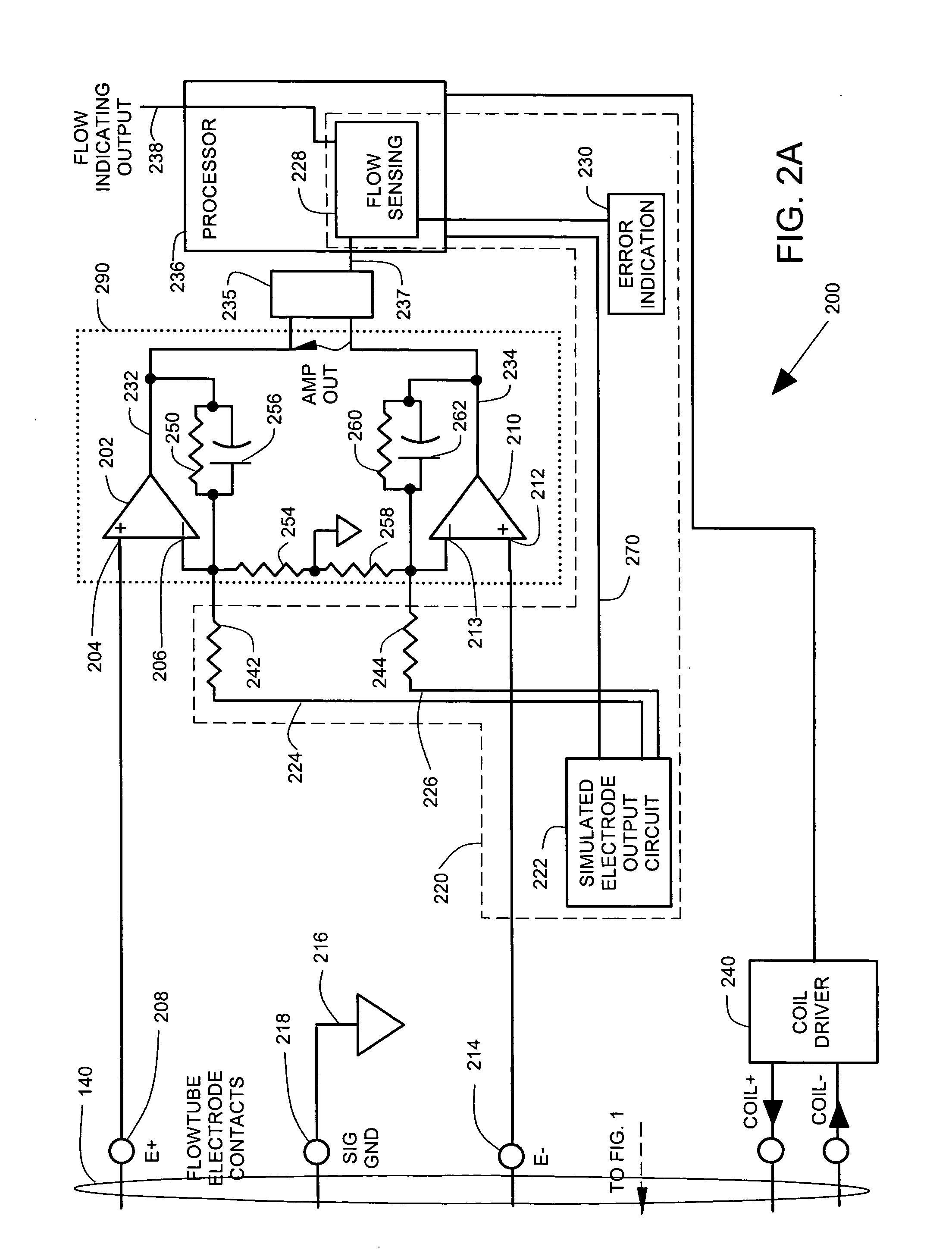
[0012] In the embodiments described below, a magnetic flowmeter is provided with a simulator that is built into a magnetic flowmeter transmitter. The simulator provides simulated electrode outputs for testing the active electronics in the magnetic flowmeter transmitter and for providing an error indication if the active electronics are malfunctioning. This error indication enables service personnel to quickly ascertain whether a flowmeter malfunction is due to a transmitter problem or a flowtube and cabling problem. The simulator can operate automatically, or can be activated by a command keyed in by service personnel.

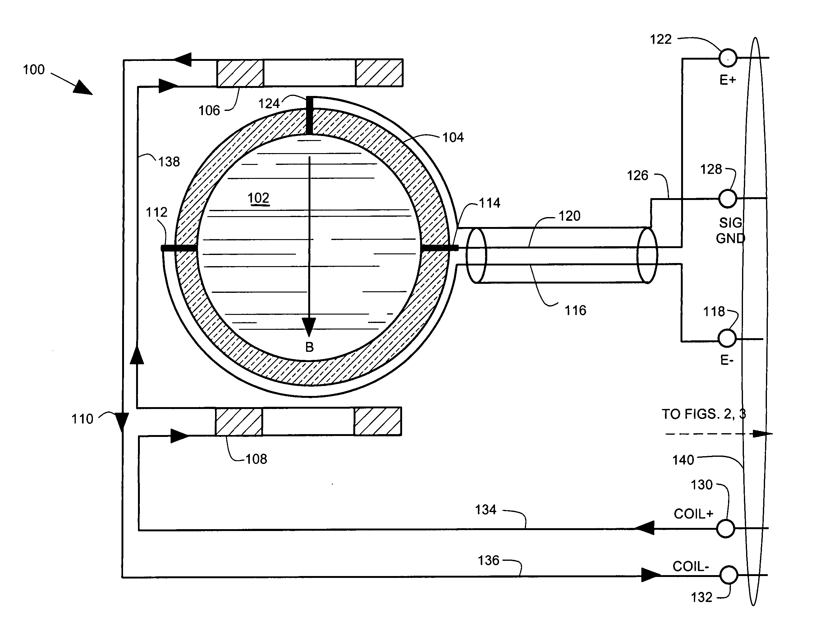
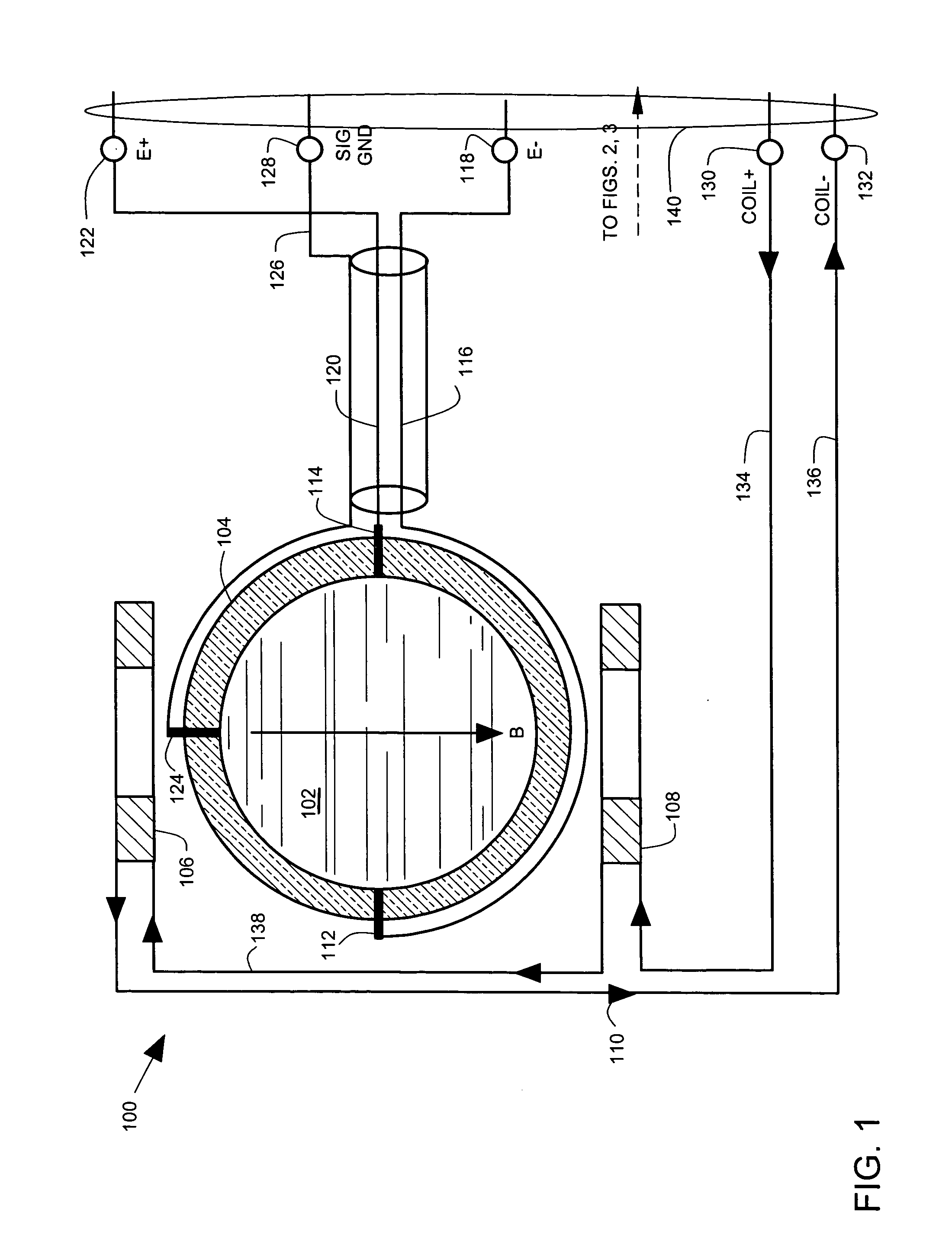
[0013]FIG. 1 illustrates a magnetic flowmeter flowtube assembly 100. The flowtube assembly 100 carries a flow of a liquid 102 through a conduit 104. Magnet coils 106, 108 carry an electric current 110 that produces a magnetic field B in the liquid 102. As the liquid 102 flows through the magnetic field B, a potential difference is generated in the liquid 102 according...


PUM


Abstract

A magnetic flowmeter transmitter includes a differential amplifier that senses an additive combination of actual flowmeter electrode outputs and simulated electrode outputs. The differential amplifier provides an additive amplifier output. A simulator provides the simulated electrode outputs. The simulator senses the additive amplifier output and provides an error indication when the additive amplifier output is outside a normal range.

Description

FIELD OF THE INVENTION [0001] The present invention relates to diagnostics of magnetic flowmeters. BACKGROUND OF THE INVENTION [0002] Magnetic flowmeters are used for liquid flow measurements in fluid processing installations such as chemical plants, food processing plants and pulp and paper plants. The magnetic flowmeter includes a flowtube assembly that is mounted in a piping system. The magnetic flowmeter also includes a transmitter that is connected to the flowtube assembly by a cable, or the transmitter can be integrally mounted to the flowtube assembly. [0003] Magnetic flowmeters are subject to failure due to extremes of temperature, vibration, chemical corrosion and the like. When a failure occurs, there is a need to rapidly diagnose the failure and replace a damaged part of the system. Ascertaining which portion of a magnetic flowmeter has failed can be difficult, particularly when the flowtube assembly is mounted in an inaccessible location. There is a desire to automate fa...

Claims


Application Information

Patent Timeline
Patent Type & Authority Applications(United States)
IPC IPC(8): G01F1/00
CPCG01F1/58G01F25/0007G01F25/10G01F1/60
Inventor COURSOLLE, THOMAS P.WEBB, ANNETTE M.
Owner MICRO MOTION INC
Why Eureka
Try Eureka