Multiscale multidimensional well log data inversion and deep formation imaging method

a multi-dimensional, well-log data technology, applied in the direction of instruments, borehole/well accessories, surveys, etc., can solve the problems of inability to accurately determine the formation resistivity using multi-array resistivity data, time-consuming and laborious 2-d inversion techniques, and inability to accurately determine the formation resistivity of thin invaded formations

Active Publication Date: 2006-05-04
BAKER HUGHES INC
View PDF20 Cites 30 Cited by
  • Summary
  • Abstract
  • Description
  • Claims
  • Application Information

AI Technical Summary

Benefits of technology

[0013] Another embodiment of the invention is an apparatus for determining a property of an earth formation. The apparatus includes a logging tool conveyed into a borehole in the earth formation, the logging tool obtaining two or more subsets of array data indicative of the property, each of the subsets having an associated resolution. The apparatus also includes a processor which processes a first subset of the array data to give a first model, and using the first model and by processing another subset of the array data, obtains a 2-D layered model of the formation, a 3-D model of the formation, and / or a 2-D image of the formation. The property may be a resistivity of the earth formation. The logging tool may be a multiarray induction logging tool, a multicomponent induction logging tool or a galvanic logging tool. One of the subsets may have a different vertical and / or horizontal resolution than another of the subset. The logging tool may be conveyed into the borehole on a wireline, a drilling tubular or a slickline.

Problems solved by technology

This single model approach has limitations when executing either joint or sequential inversions.
One problem with inversion is that the earth is characterized by, at the very least, a 2-D model (layers with radial changes in resistivity within each layer).
A rigorous 2-D inversion technique would be quite time consuming and impractical for wellsite implementation.
The main shortcoming of this method, as indicated by the authors, is it may provide incorrect results for the thin invaded formations.
Therefore, to complete the interpretation, an additional, time consuming rigorous 2-D inversion step is required.
By not accounting for the vertical resolution differences of the input subarray data, both joint or sequential inversion procedures may lead to unstable and incorrect results in thin invaded formations.

Method used


Image

  • Multiscale multidimensional well log data inversion and deep formation imaging method
  • Multiscale multidimensional well log data inversion and deep formation imaging method
  • Multiscale multidimensional well log data inversion and deep formation imaging method

Examples


Embodiment Construction

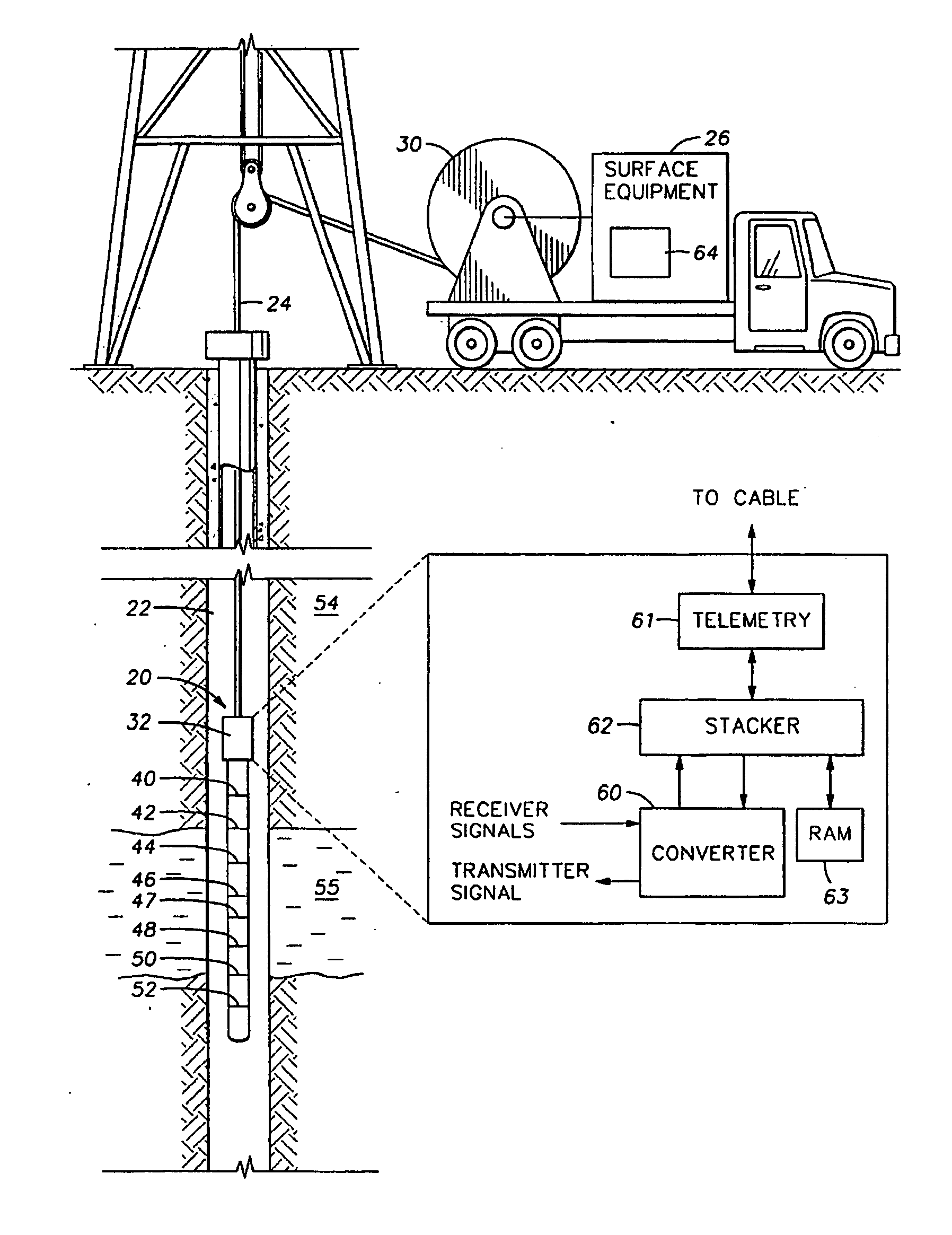
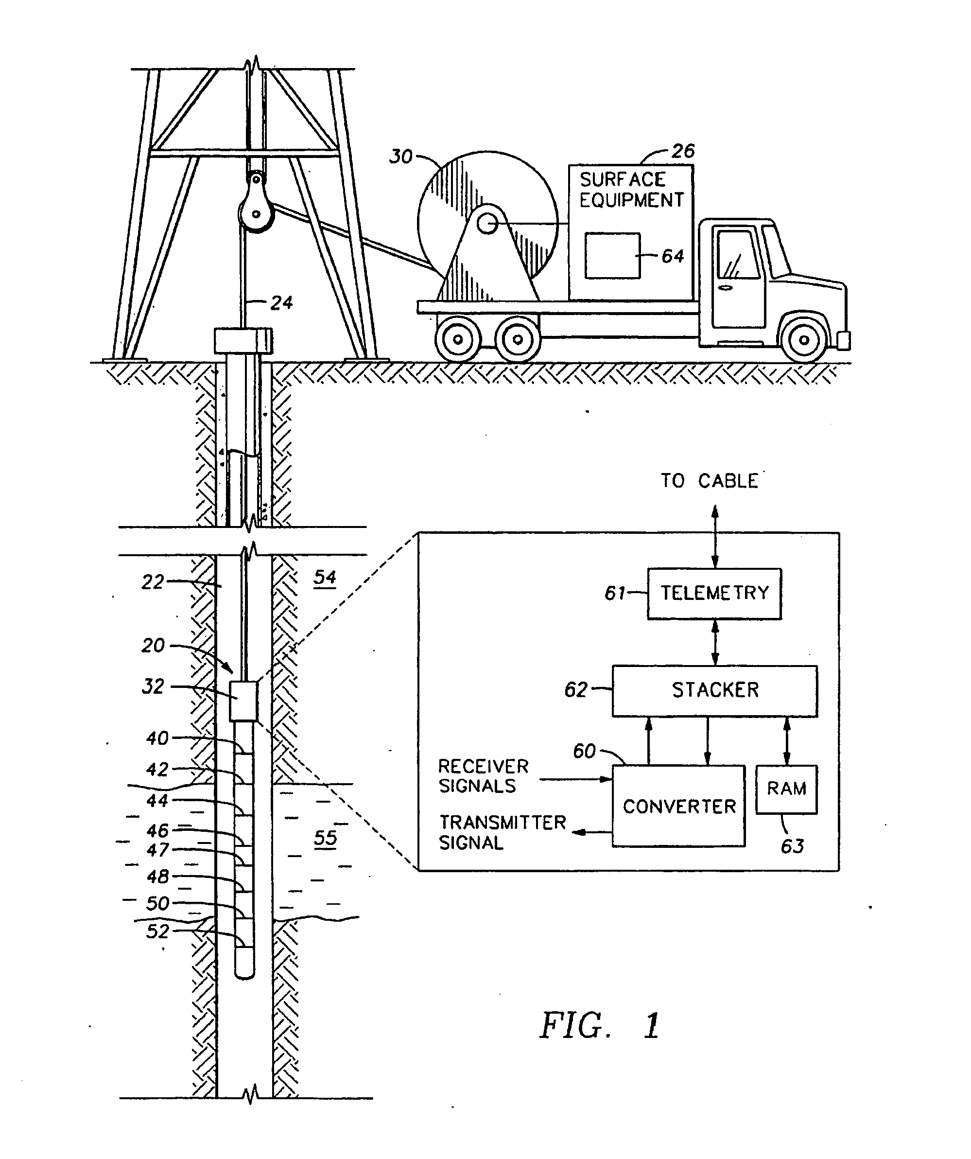
[0029] Referring now to FIG. 1, an exemplary induction logging tool 20 suitable for use with the method of the present invention is shown positioned in a borehole 22 penetrating earth formations 54. The tool 20, which is suspended in the borehole 22 by means of a wireline cable 24, includes a borehole sonde 34 and an electronic circuitry section 32. The tool 20 is lowered into the borehole 22 by a cable 24, which preferably passes over a sheave 30 located at the surface of the borehole 22. The cable 24 is typically spooled onto a drum (not shown). The cable 24 includes insulated electric conductors for transmitting electrical signals. The electronic circuitry section 32 of the tool 20 receives signals from the sonde section 34 and typically comprises a processor. Some or all of the processing may also be done by a surface processor, or by a remote processor linked to the wellsite by a suitable satellite link.

[0030] The sonde 34 preferably includes a plurality of coils 40-52. Coil 4...


PUM


Abstract

Different subsets of multiarray resistivity measurements are inverted using a corresponding resistivity model. The models are selected based at least in part on the resolution of the measurements. Results of the inversion are combined to give a single model consistent with the resolution and depth of penetration of each subset of the multiarray data.

Description

CROSS-REFERENCES TO RELATED APPLICATIONS [0001] This application claims priority from U.S. Provisional Patent Application Ser. No. 60 / 625,267 filed on Nov. 4, 2004.BACKGROUND OF THE INVENTION [0002] 1. Field of the Invention [0003] The invention is related generally to the field of interpretation of measurements made by well logging instruments for the purpose of determining the properties of earth formations. More specifically, the invention is related to a method for determination of formation resistivity using multi-array resistivity data. [0004] 2. Background of the Art [0005] Electromagnetic induction, wave propagation, and galvanic logging tools are commonly used for determination of electrical properties of formations surrounding a borehole. These logging tools give measurements of apparent resistivity (or conductivity) of the formation that when properly interpreted are diagnostic of the petrophysical properties of the formation and the fluids therein. [0006] The physical pr...

Claims


Application Information

Patent Timeline
Patent Type & Authority Applications(United States)
IPC IPC(8): G06G7/56E21B47/12E21B47/00
CPCG01V1/40G01V3/28
Inventor FRENKEL, MICHAEL A.
Owner BAKER HUGHES INC
Why Eureka
Try Eureka