Integrally molded surface fastener, and continuous production method and continuous production device therefor
- Summary
- Abstract
- Description
- Claims
- Application Information
AI Technical Summary
Benefits of technology
Problems solved by technology
Method used
Image
Examples
first embodiment
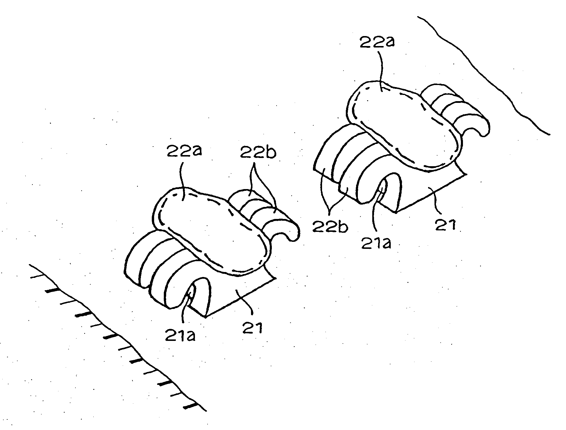
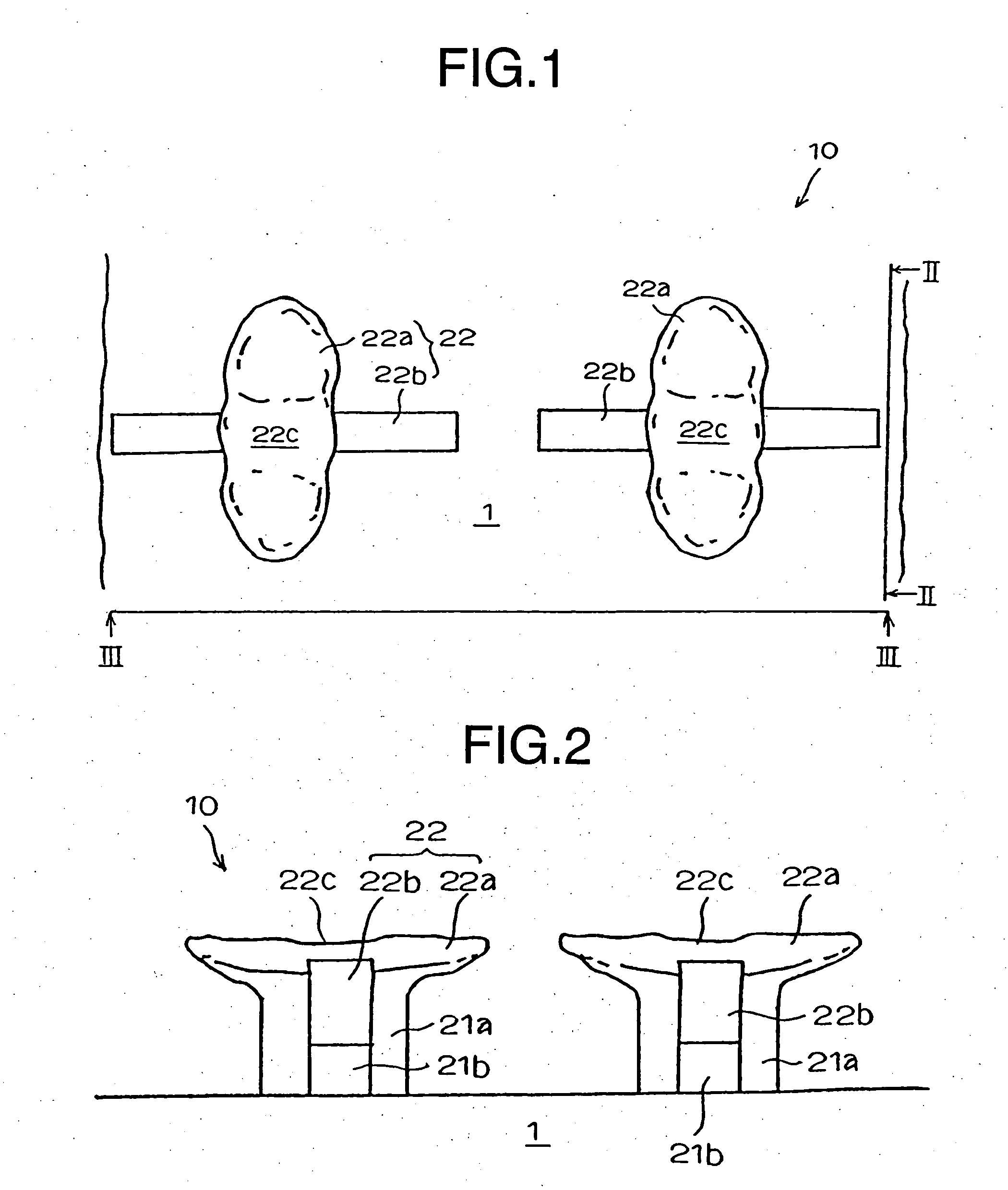
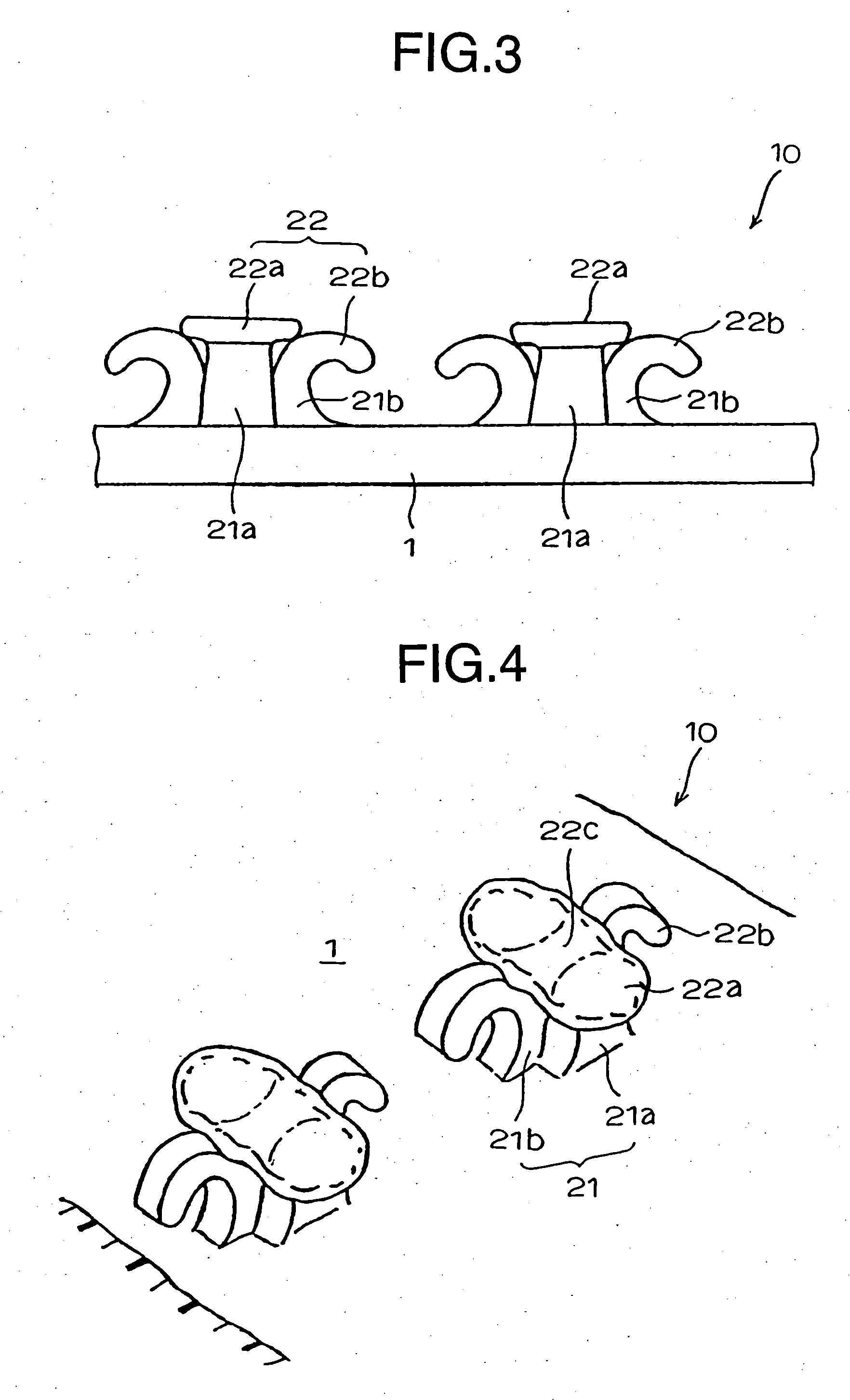
[0067]FIG. 1 is a partial plan view of a molded surface fastener having typical engaging element configuration according to the present invention. FIG. 2 is a sectional view taken along the line II-II, FIG. 3 is a sectional view taken along the line III-III and FIG. 4 is a perspective view of part of the molded surface fastener as seen from obliquely above.
[0068] An engaging element 2 of this embodiment comprises a pillar portion 21 rising vertically from a surface of a flat base member 1 and at its top end, an engaging head 22 including a first engaging portion 22a which extends in wing-like construction in opposite directions to each other, perpendicular to the molding direction (y direction) and a hook-like second engaging portion 22b which extends in opposite directions to each other with respect to the molding direction. The pillar portion 21 includes a first pillar portion 21a and a second pillar portion 21b, which are formed integrally such that they intersect each other at r...
second embodiment
[0113] FIGS. 14 to 16 show the present invention. According to this embodiment (not shown), on the preliminary molding stage, the preliminarily molded first engaging portion erected linearly, which is a composition of the preliminarily molded element, is divided to ½ sections in the direction perpendicular to the molding direction (right and left) and for each section, hook-like preliminarily molded second engaging portions are extended in parallel to each other in opposite directions to each other along the molding direction from the first engaging portion.
[0114] By passing the preliminarily molded surface fastener having the preliminarily molded element 2′ having such a configuration through the with-heat pressing unit 150 shown in FIG. 8, which is a producing portion, the engaging element 2 having a configuration shown in FIGS. 14 to 16 is molded. For this engaging element 2, by pressing the preliminarily molded first engaging portion of the preliminarily molded element from abov...
third embodiment
[0115]FIGS. 17 and 18 show the present invention. As for the configuration of the engaging element 2 of this embodiment, as understood from the figures, a pair of the second engaging portions 22b extending in parallel back and forth in one direction are formed and the first engaging portion 22a composed of wing-like thin plate extends to the right and left across the right and left second engaging portions 22b in pair.
[0116]FIGS. 19A and 19B show a further modification of the second embodiment. According to this modification, the first engaging portion 22a composed of the wing-like thin plate and the second engaging portion 22b composed of hook piece are disposed such that they intersect at right angle as seen in a plan view and they provide a substantially letter L shape because they extend in each single direction with respect to the pillar portion 21 as seen in a top view. In case of this modification, because the first engaging portion 22a and the second engaging portion 22b do ...
PUM
| Property | Measurement | Unit |
|---|---|---|
| Time | aaaaa | aaaaa |
| Angle | aaaaa | aaaaa |
| Moldable | aaaaa | aaaaa |
Abstract
Description
Claims
Application Information
 - R&D
- Intellectual Property
- Life Sciences
- Materials
- Tech Scout
- Unparalleled Data Quality
- Higher Quality Content
- 60% Fewer Hallucinations
Browse by: Latest US Patents, China's latest patents, Technical Efficacy Thesaurus, Application Domain, Technology Topic, Popular Technical Reports.
© 2025 PatSnap. All rights reserved.Legal|Privacy policy|Modern Slavery Act Transparency Statement|Sitemap|About US| Contact US: help@patsnap.com


