Optical projection tomography microscope

a tomography microscope and optical projection technology, applied in the field of optical systems, can solve the problems of unsuitable rotational speed, unknown mechanism, and limited polymer gripper use,

Inactive Publication Date: 2006-05-11
UNIV OF WASHINGTON +1
View PDF77 Cites 27 Cited by
  • Summary
  • Abstract
  • Description
  • Claims
  • Application Information

AI Technical Summary

Problems solved by technology

Unfortunately, known mechanisms do not provide a rotational joint that suitably allows high rotational speed combined with ease of use and stability, especially in the case where the cylindrical specimen container comprises a fragile device such as a mi...

Method used


Image

  • Optical projection tomography microscope
  • Optical projection tomography microscope
  • Optical projection tomography microscope

Examples


Embodiment Construction

[0016] The invention is described herein with respect to specific examples relating to biological cells; however, it will be understood that these examples are for the purpose of illustrating the principals of the invention, and that the invention is not so limited. For illustrative purposes, an object such as a biological cell may be labeled with at least one tagged molecular probe, and the measured amount and location of this probe may yield important information about the disease state of the cell, including, but not limited to, various cancers such as lung, colon, prostate, breast, cervical and ovarian cancers, or infectious agents.

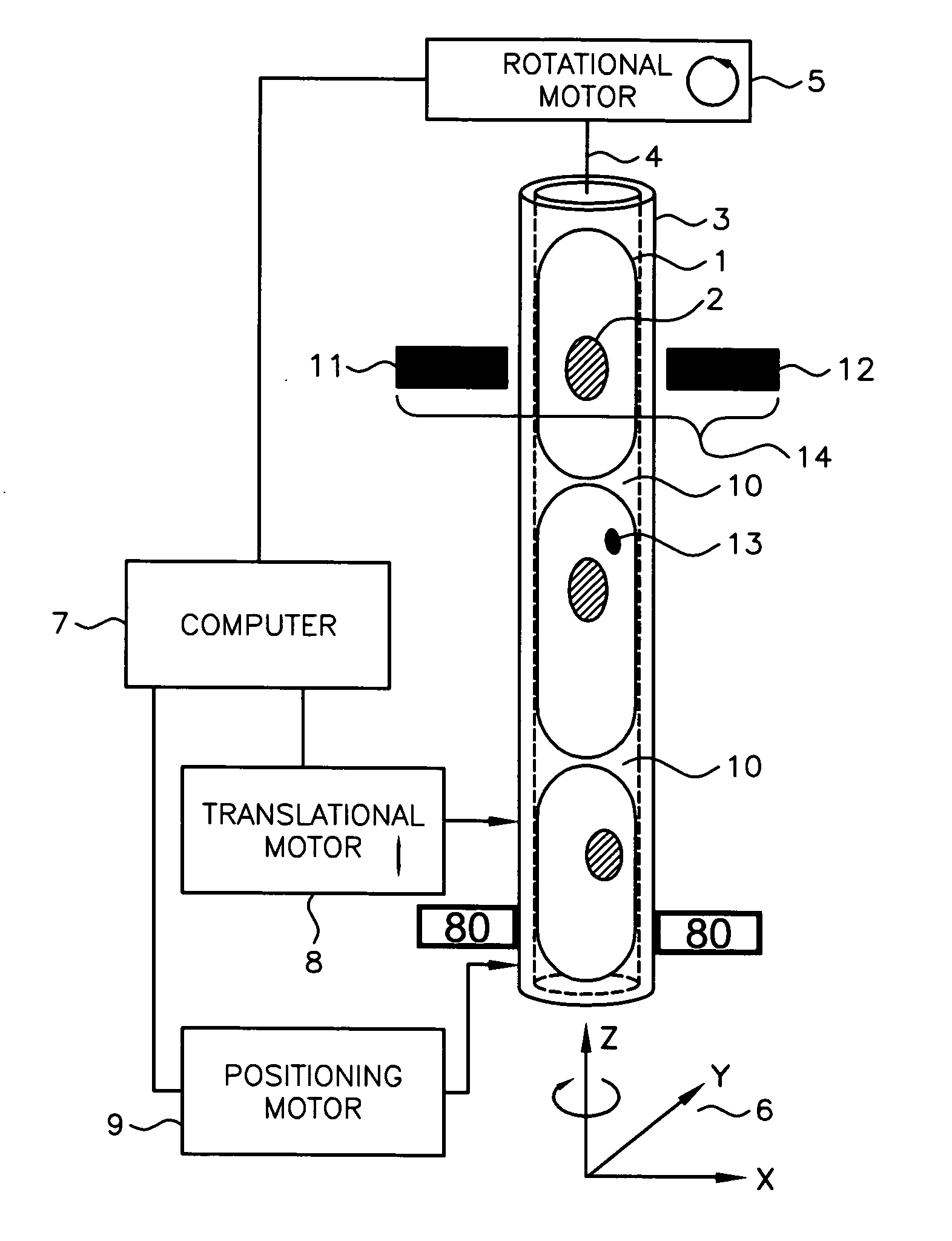
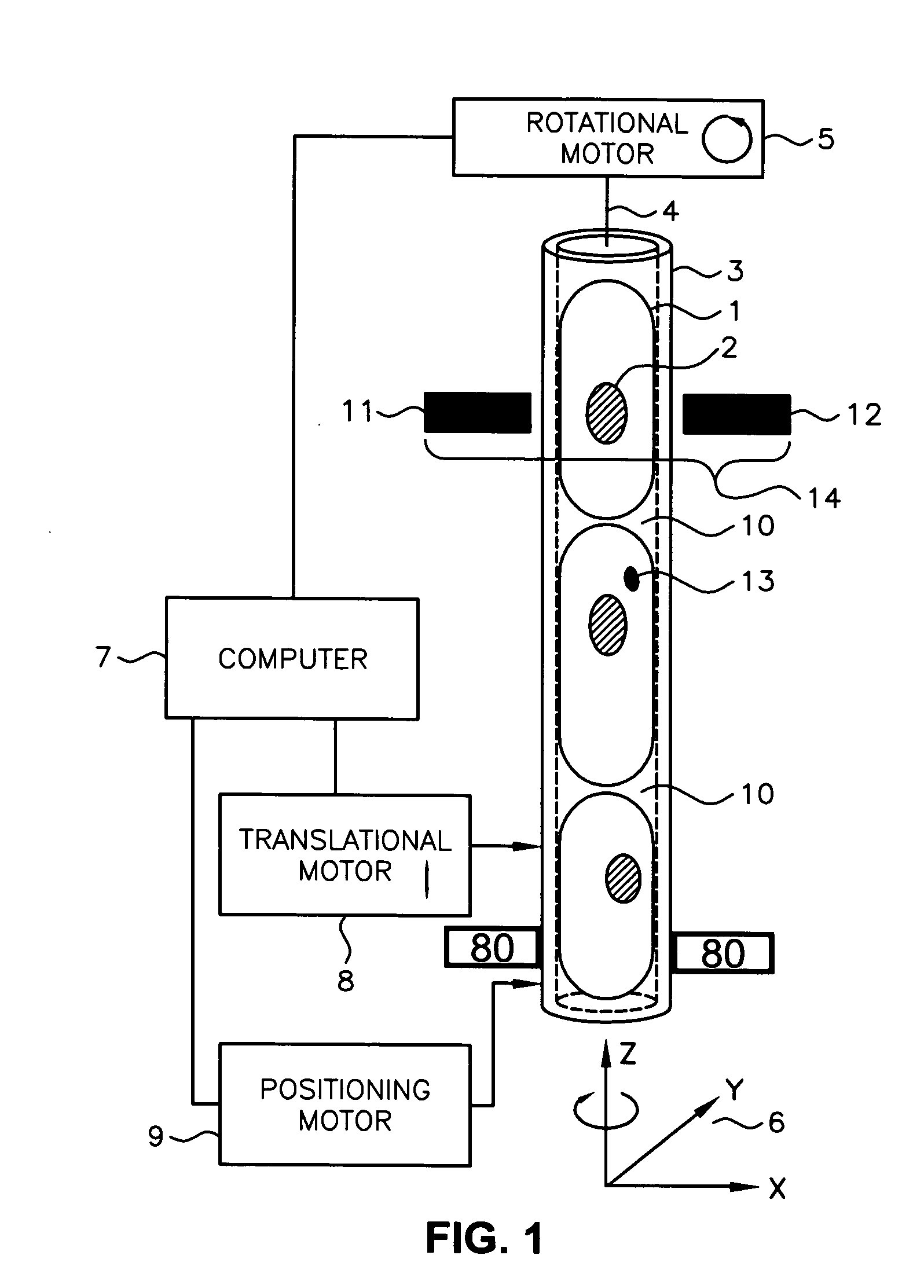
[0017] Referring now to FIG. 1, there shown schematically is an example illustration of cells packed into a cylindrical container as contemplated by an embodiment of the present invention. In this example embodiment, a section of the cylindrical container 3 is filled with cells 1 that are packed rigidly into the tube. Each of the cells may include a ...


PUM


Abstract

A rotational system including a cylindrical container with a cylindrical container axis. The cylindrical container is inserted into at least one pair of opposing polymer grippers. A motor is coupled to rotate the cylindrical container.

Description

FIELD OF THE INVENTION [0001] The present invention is related to optical systems and, more particularly, to optical systems for extended depth-of-field imaging through a cylindrical specimen container. BACKGROUND OF THE INVENTION [0002] An optical tomographic device is intended to produce three-dimensional reconstructions of specimens contained in a capillary tube by providing a multitude of “shadowgrams.” A shadowgram, also known in the art as a projection, is a measure of light attenuation along a set of ray paths through the specimen. [0003] To obtain a three-dimensional representation of an object, a microscope objective is axially scanned such that its plane of focus scans through the specimen's thickness. The focal plane of the objective lens can be moved through the specimen while the detector is located in the microscope's image plane. Thus, a projection image can be compiled from a set of discrete focal planes within the specimen, and this compilation is called a pseudo-pr...

Claims


Application Information

Patent Timeline
IPC IPC(8): G01N30/00
CPCB82Y10/00B82Y20/00G01N15/147G01N15/1475G01N2021/1787G02B21/0004
Inventor FAUVER, MARK E.NELSON, ALAN C.
Owner UNIV OF WASHINGTON
Why Eureka
Try Eureka