
High precision gas bearing split-axis stage for transport and constraint of large flat flexible media during processing

a gas bearing and flexible media technology, applied in the field of methods and equipment, can solve the problems of insufficient detection of defects, high mechanical precision, and many production defects, and achieve the effect of reducing the tact time and the tact tim

Inactive Publication Date: 2006-05-11
ORBOTECH LTD
View PDF22 Cites 81 Cited by
  • Summary
  • Abstract
  • Description
  • Claims
  • Application Information

AI Technical Summary

Benefits of technology

The present invention is a testing or repair platform that can accommodate larger media plates while maintaining precision frame and reference surfaces. This is achieved by using a split-axis design, which separates the main media transport axis into sections with different precision requirements. The invention reduces the system inspection tact time, which is the time required to load, align, process, and unload the media. The invention also addresses the size limitations and cost implications of direct scaling of the monolithic granite base plate approach to higher generation media plates. The resulting scalable mechanical stage meets the requirements of a high performance inspection / repair application. The invention provides a high performance inspection / repair system for the transport, positioning, and constraint of flat flexible media that meets industry precision requirements.

Problems solved by technology

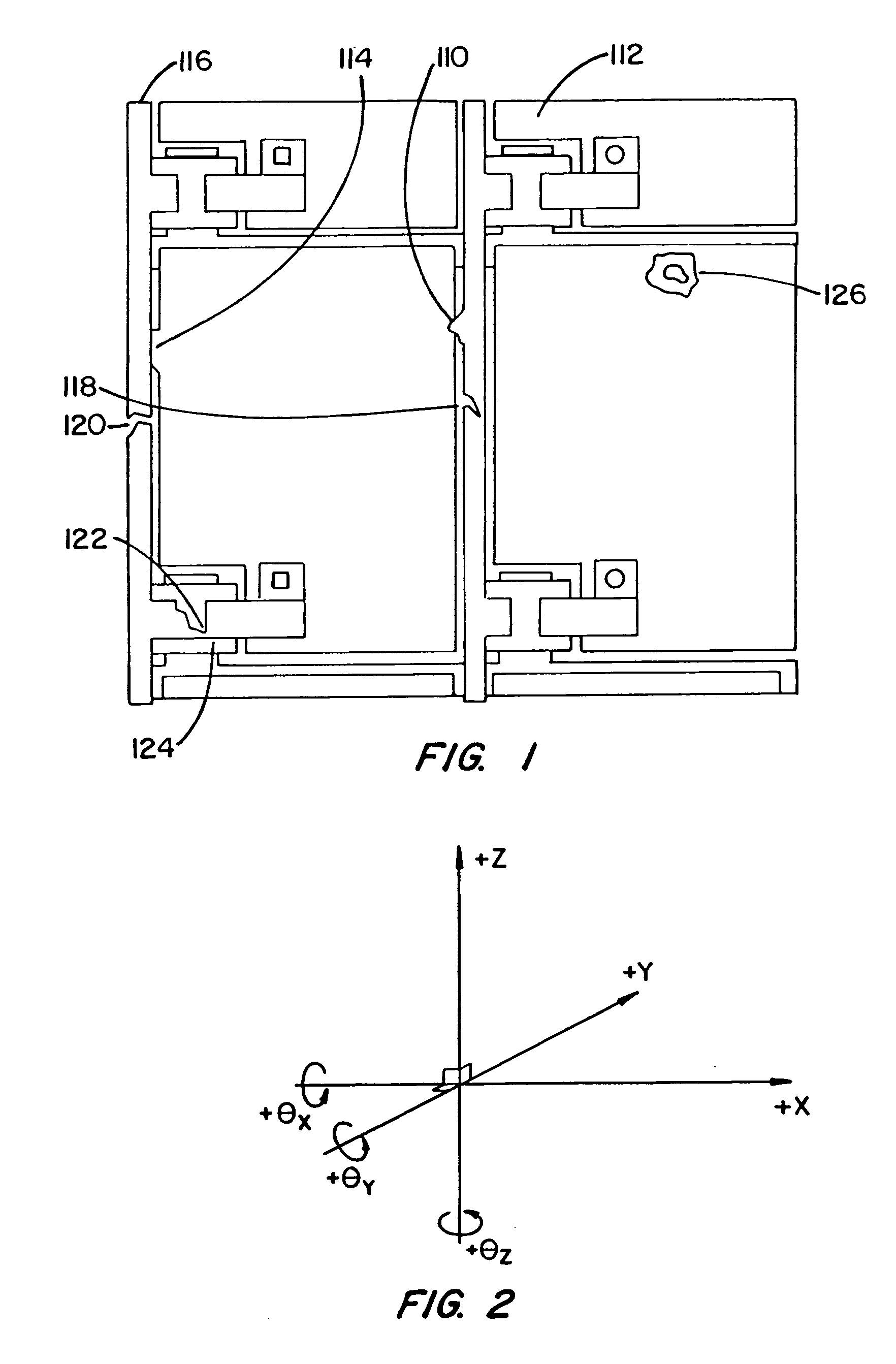
During each of these stages, and at various steps within a stage, many production defects may occur, that have electronic and / or visual implications on the final performance of the LCD product.
In the preferred application domain such as the inspection and repair of TFT LCD panels, the defects subject to detection and repair can be as small as several microns in size, placing demanding defect detection limits on inspection and repair systems.
Moreover, mere detection of defects is insufficient.
Motion along each of these degrees of freedom may be intentional (due to actuation) or unintentional (due to mechanical inaccuracy in the system).
However, due to the inability to achieve perfect mechanical control, the uncontrolled movements along any of these remaining degrees of freedom lead to the system exhibiting a reduced mechanical precision.
Note that each of these configurations will shift the precision requirements onto another part of the stage, will impact the size of the stage and will also result in a particular distribution of mechanical complexity within the system.
In practice, apart from the aforementioned positional accuracy and repeatability requirements, there may be more complex relationships involved.
This results in much lower linear and angular errors for the shuttle as compared to the errors implied by those supporting surfaces.
Although the concept has also been extended to the AOI and electrical functional inspection of the glass plates deposited by TFT / LCD panels, limitations in this particular domain have been the weight and size.
The maximum feasible size achievable by this configuration is primarily limited by the weight and size of the required monolithic granite base plate which can be feasibly manufactured, stored, transported and installed.
This is due to the weight, shape, and size of the instrument, which exceed the typical truck and plane cargo space capacity.
The result is an exponential increase in the cost of transporting the instrument to its final destination.
However, with the increasing size of the media panels to be inspected, this approach quickly becomes impractical due to the unmanageable size of the stage and the escalating cost that arises.
However, the patent does not address the required complexity and precision requirements and the associated cost implications of the inspection / processing station.
However, no attempt is made to constrain the flatness of the conveyed media.

Method used


Image

  • High precision gas bearing split-axis stage for transport and constraint of large flat flexible media during processing
  • High precision gas bearing split-axis stage for transport and constraint of large flat flexible media during processing
  • High precision gas bearing split-axis stage for transport and constraint of large flat flexible media during processing

Examples


Embodiment Construction

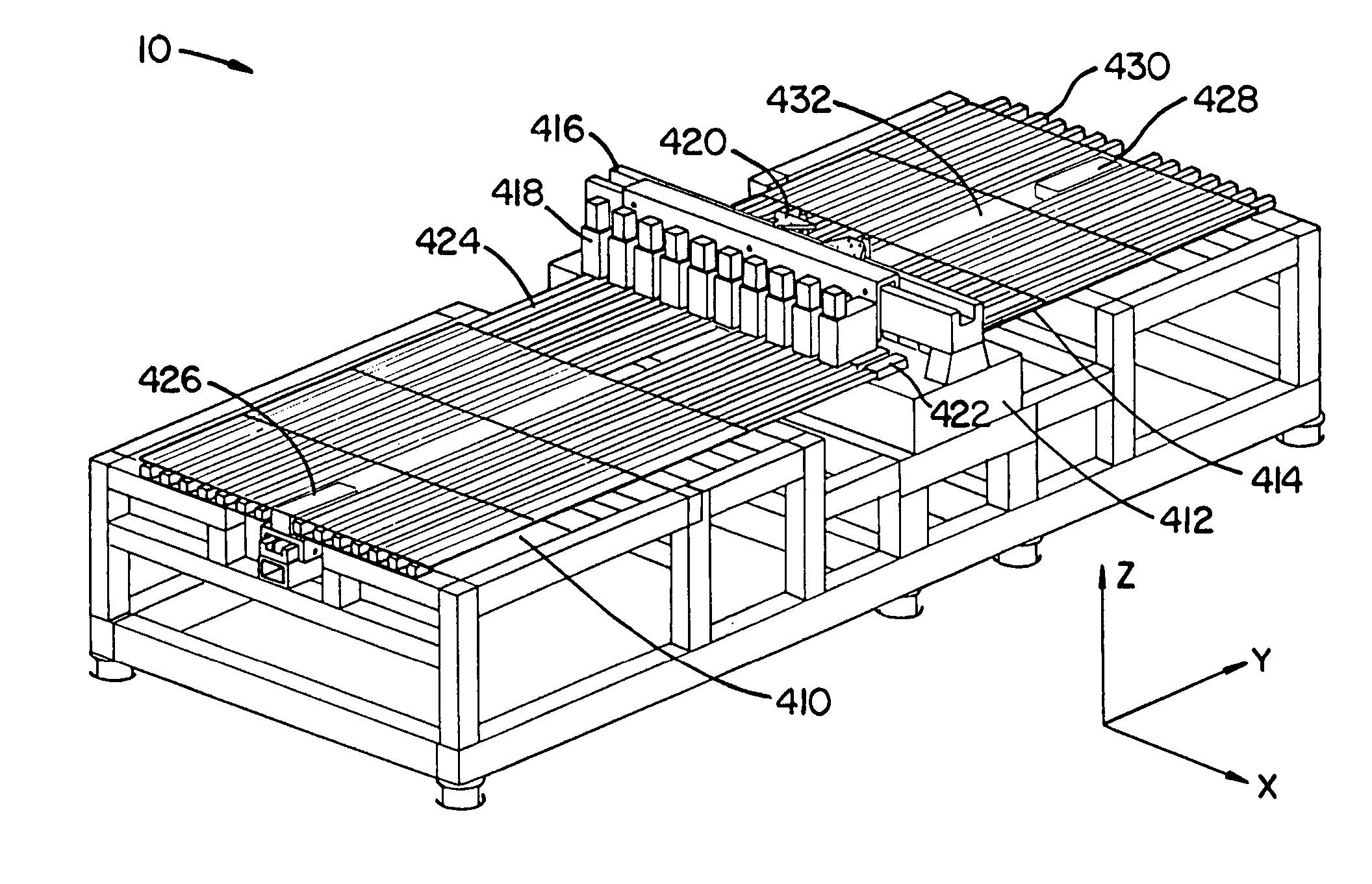
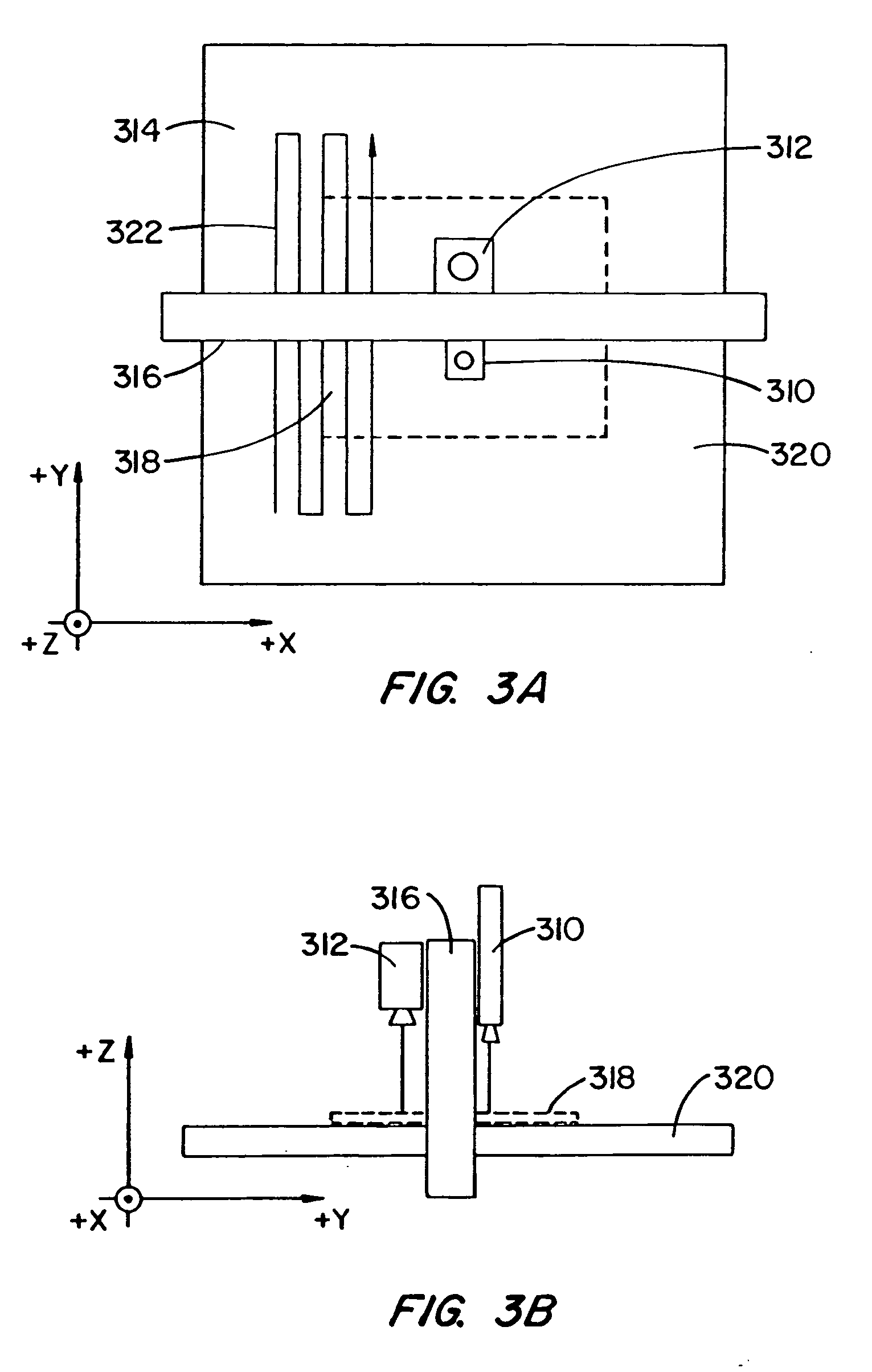
[0050] Referring to FIG. 4A, the system 10 according to the invention has typically three partitions or sections 410, 412, and 414, in which the smaller size mid-web partition 412 is designed to meet the highest mechanical precision requirements for the partitions. The up-web stage partition 410 and down-web stage partition 414 are designed to support and transport flat media 432 into and out of the precision mid-web partition 412 while minimizing interference with the precision operation of the mid-web partition. An air cushion or gas bearing based flat flexible media support mechanism provided by the combined up-web, mid-web and down-web sections 410, 412, and 414 obviates the need for rigid vacuum chucks that would immobilize the media during transport and testing / repair. Only the mid-web section 412 incorporates a monolithic granite base plate surface 422 and attached gantry 416, resulting in a dramatic reduction in size and weight of the required granite block. This mid-web sec...


PUM

PropertyMeasurementUnit
thicknessaaaaaaaaaa
thicknessaaaaaaaaaa
depth of fieldaaaaaaaaaa

Abstract

A modular split-axis stage is used to inspect and / or repair large flat glass media suitable for LCD / TFT applications. Low-precision air table sections are detachably mounted to a centrally located, high-precision granite inspection / repair section. Glass media held by a vacuum contact is transported on air cushions from the up-web air table to the central inspection / repair section. Vacuum nozzles integrated with porous medium pads precisely control the height of the flexible media above the central section during inspection or repair. Embodiments includes structures in which the media is either stationary or moving during inspection / repair. A first media can be loaded / unloaded while a second media is undergoing inspection or repair in a pipelined operational mode.

Description

CROSS-REFERENCES TO RELATED APPLICATIONS [0001] This application is a divisional of U.S. patent application Ser. No. 10 / 637,215 filed Aug. 8, 2003.BACKGROUND OF THE INVENTION [0002] This invention relates to methods and apparatus for handling large flat and generally very thin flexible objects, and specifically to methods and apparatus for transporting, supporting, positioning, and constraining, with high mechanical precision, large flat flexible media. More specifically, this invention relates to the use of such transport and constraint mechanisms and techniques for automated optical inspection (AOI), electrical functional inspection (e.g., Voltage Imaging or VI) or automated repair (AR) of large flat, flexible and possibly patterned media, such as glass panels deposited with structures used to form thin film transistor (TFT) arrays (which are the main active component of liquid crystal flat panel displays (LCD). Although the invention is applicable to the general case of inspectio...

Claims


Application Information

Patent Timeline
Patent Type & Authority Applications(United States)
IPC IPC(8): G01N19/00G01B21/00B65G49/06G01N21/95G02F1/13G02F1/1333G02F1/1362G02F1/1368H01L21/677
CPCB65G49/061B65G49/063B65G2249/04G01N21/896G01N21/95G01N2021/8867G01N2021/9513G02F1/136259H01L21/67721G01N21/8903E02D17/207A01C1/044
Inventor WEISS, ADAMSARANLI, AFSARGHELMAN, EDUARDOBALDWIN
Owner ORBOTECH LTD
Learn More