Data processing unit and pattern forming method

a data processing unit and pattern forming technology, applied in the field of data processing apparatus and image forming, can solve the problems of fabric easily being misaligned, difficult to form embroidery patterns, and difficult to achieve predetermined alignment of fabrics

Active Publication Date: 2006-05-11
BROTHER KOGYO KK
View PDF10 Cites 39 Cited by
  • Summary
  • Abstract
  • Description
  • Claims
  • Application Information

AI Technical Summary

Problems solved by technology

In such case, troubles may occur between the print head and the frame, such that the print head may interfere the frame when the frame is detached from or attached to the printing device, or the print head may interfere with the frame to be driven.
In such case, it is difficult to form the embroidery pattern and the printed pattern in a predetermined location with respect to each other.
However, as the other frame is not provided with any mechanism to adjust the position of the fabric with respect to the pattern that is already formed on the fabric, having the fabric in the predetermined alignment has been difficult.
However, even in such a method, the fabric can be easily be misaligned from the predetermined position, and the above-described problem cannot be easily solved.
Therefore, in order to prevent the misalignment, a user is required to repeatedly adjust the position of the fabric with respect to the other frame by reattaching the fabric to the other frame, which may be time consuming and troublesome.
When the size of the one of the frames of the embroidery sewing machine and the printing device and the size of the other frame are not identical, even with a reference mark provided to the fabric, having the fabric in the predetermined position with respect to the other frame is even more difficult, as no positioning mechanism to align the fabric in position is provided to the other frame.

Method used


Image

  • Data processing unit and pattern forming method
  • Data processing unit and pattern forming method
  • Data processing unit and pattern forming method

Examples


embodiments

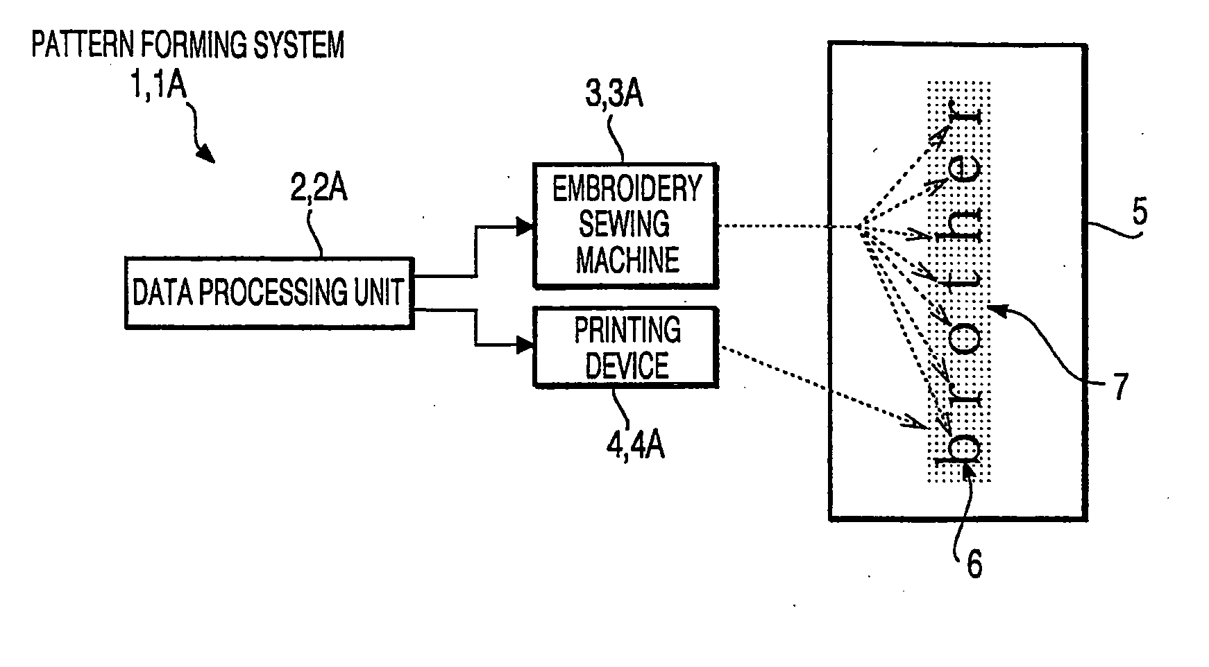
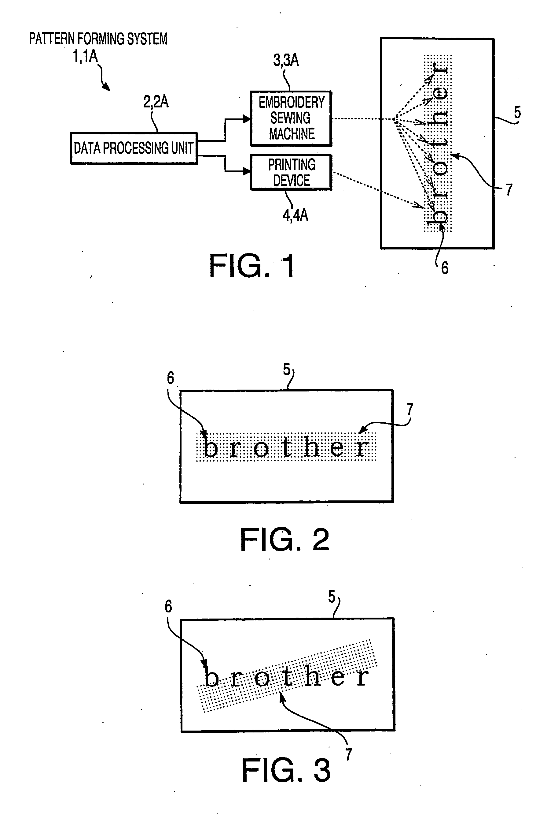
[0118] As shown in FIG. 1, pattern forming systems 1, 1A are provided with data processing units 2, 2A that include personal computers, embroidery sewing machines 3, 3A, and inkjet printing devices 4, 4A. The data processing units 2, 2A supply embroidery data (second image data) to the embroidery sewing machines 3, 3A and print data (first data) to the printing devices 4, 4A. Further, the data processing units 2, 2a respectively form an embroidery pattern 6 (for example, ‘brother’) by using the embroidery sewing machines 3, 3A based on the embroidery data and form a printed pattern 7 (for example, a rectangular pattern in the background of ‘brother’) by using the printing devices 4, 4A based on the print data. It should be noted that the data processing units 2, 2A can be equipped to the embroidery sewing machines 3, 3A respectively or to the printing devices 4, 4A respectively.

[0119] Each of the embroidery sewing machines 3, 3A and the printing devices 4, 4A is provided with a ded...

first embodiment

[0120] In the first embodiment, the pattern forming system 1 is configured to form the embroidery pattern 6 and the printed pattern 7 in a predetermined alignment with respect to each other on the fabric 5 with the printed pattern 7 formed on the fabric 5 by using the printing device 4 and the embroidery pattern 6 succeedingly formed on the fabric 5 by using the embroidery sewing machine 3.

[0121] [Embroidery Sewing Machine]

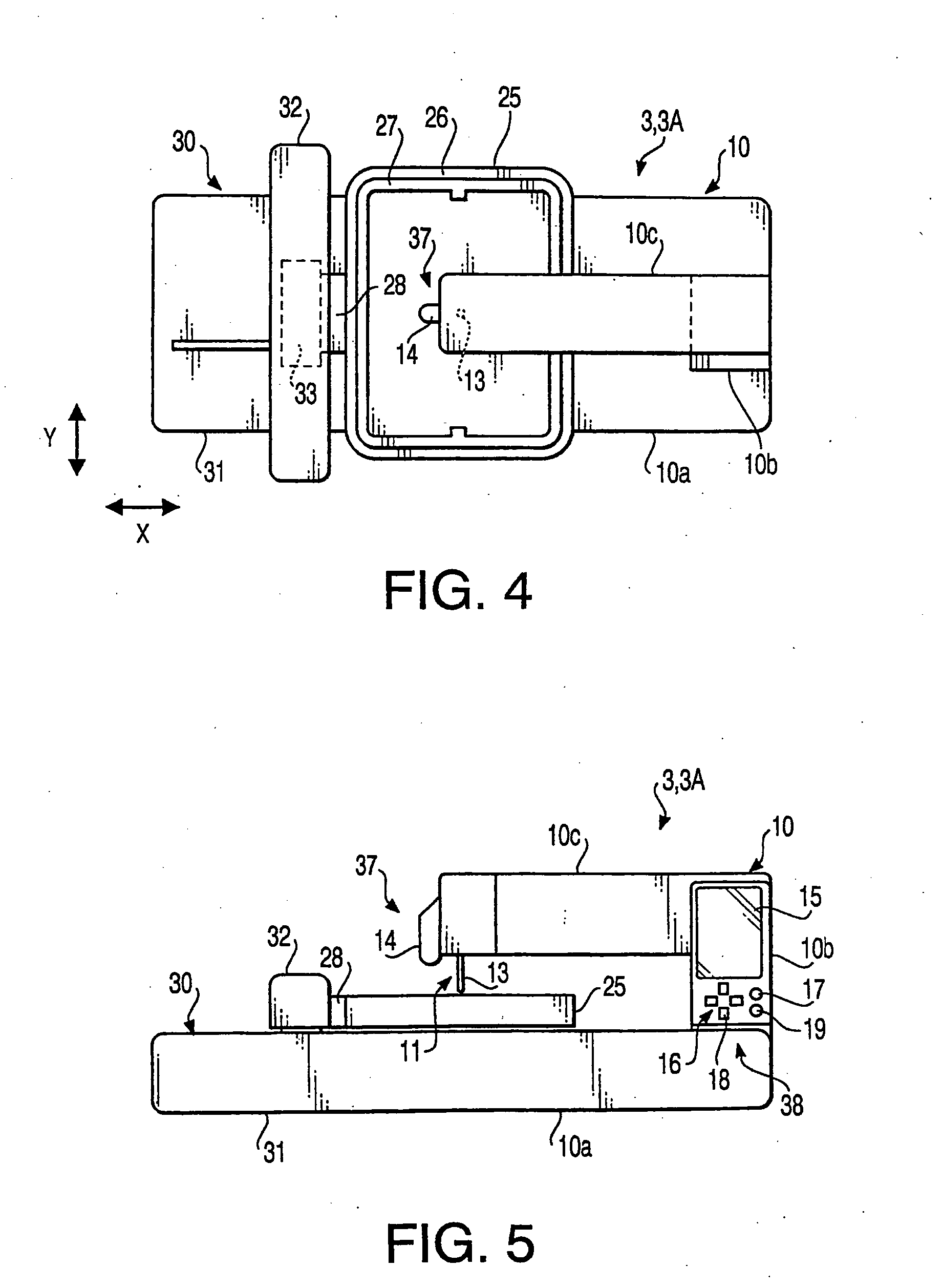
[0122] Hereinafter, the embroidery sewing machine 3 will be described. As shown in FIGS. 4 through 6, the embroidery sewing machine 3 includes a machine body 10 having a sewing system 11 with a needle 13, a frame 25 to which the fabric 5 is removably held, and a frame drive unit 30 that drives the frame 25 in two directions (i.e., in an X direction and in a Y direction) respectively.

[0123] The machine body 10 includes a bed 10a, a pillar 10b, and an arm 10c. The bed 10a is provided with the frame drive unit 30. The sewing system 11 is equipped with a motor 12, a...

second embodiment

[0185] In the second embodiment, as shown in FIG. 25, the first step and the second step are similar to the first step and the second step of the first embodiment.

[0186] In the third step, the printing device 4 forms the printed pattern 7 on the fabric 5 that is held by the frame 55 of the printing device 4 based on the print data received from the data processing unit 2. Further, before or after the printed pattern 7 is formed on the fabric, the printing device 4 prints the two reference marks 8, 9 based on the reference mark print data received from the data processing unit 2 (see FIGS. 26, 27). Then, as shown in FIG. 28, a template 100, which is formed with a transparent or translucent plate, is attached to the frame 55 of the printing device 4. Further, the printing device 4 prints the two reference marks 8a, 9a on the template 100 based on the reference mark print data (see FIGS. 29, 30).

[0187] Next, the fabric 5 is transferred from the frame 55 of the printing device 4 to th...


PUM


Abstract

A printing and embroidering system having a positional data appending system that is adapted to append positional data indicating positions of a first image and a second image with respect to each other to first image data representing the first image to be formed by one of printing and embroidering and second image data representing the second image to be formed by the other one of printing and embroidering, a first image forming unit with a first fabric holding member, which is adapted to form the first image based on the first image data on a fabric being held by the first fabric holding member, and a second image forming unit with a second fabric holding member, which is adapted to form the second image based on the fabric being held by the second fabric holding member, wherein the first image forming unit is provided with a mark forming system, which is adapted to form a predetermined mark represented by the positional data on the fabric, and wherein the second image forming system is provided with a misalignment eliciting system, which is adapted to elicit a misalignment between a position of the predetermined mark formed on the fabric held by the second fabric holding member and a position represented by the positional data appended to the second image data prior to forming the second image.

Description

CROSS REFERENCE TO RELATED APPLICATION [0001] This application claims priority from Japanese Patent Applications No. 2004-323501, No. 2004-323502, and No. 2004-323503, filed on Nov. 8, 2004, the entire subject matter of which are incorporated herein by reference. BACKGROUND OF THE INVENTION [0002] 1. Technical Field [0003] Aspects of the invention relate to a data processing apparatus and a method for image forming that are adapted to form an embroidery pattern in a predetermined position with respect to a printed pattern formed on a fabric with a printing device, and that are adapted to form a printed pattern in a predetermined position with respect to an embroidery pattern formed on a fabric with an embroidery sewing machine. [0004] 2. Related Art [0005] Conventionally, various embroidery sewing machines that are adapted to form embroidery patterns on fabrics by driving frames to hold the fabrics in two directions independently based on data for the embroidery patterns have been u...

Claims


Application Information

Patent Timeline
Patent Type & Authority Applications(United States)
IPC IPC(8): D05B21/00
CPCD05B19/08D05C5/00D05C7/00
Inventor KUKI, MASAKAZUKISHI, MOTOSHINAKASHIMA, HIROKAZU
Owner BROTHER KOGYO KK
Why Eureka
Try Eureka