
Control apparatus for internal combustion engine

Inactive Publication Date: 2006-05-11
TOYOTA JIDOSHA KK
View PDF4 Cites 14 Cited by
  • Summary
  • Abstract
  • Description
  • Claims
  • Application Information

AI Technical Summary

Benefits of technology

[0010] An object of the present invention is to provide a control apparatus for an internal combustion engine having first and second fuel injection mechanisms bearing shares, respectively, of injecting fuel into a cylinder and an intake manifold, respectively, that can calculate an accurate fuel variation value in a cold state and a transitional period from the cold state to a warm state when the fuel injection mechanisms share injecting the fuel.

Problems solved by technology

At a very low temperature, starting capability is impaired due to poor atomization of fuel.
Additionally, at a very low temperature, the viscosity of a lubricating oil is high and therefore a friction increases and the number of cranking revolutions decreases.
Accordingly, with a high-pressure fuel pump directly driven by an engine, a fuel pressure cannot fully be increased.
A required fuel quantity may not be supplied to the engine solely with a fuel injection valve (a main fuel injection valve) provided for injecting a fuel directly into a combustion chamber, and the starting capability may further be impaired.

Method used


Image

  • Control apparatus for internal combustion engine
  • Control apparatus for internal combustion engine
  • Control apparatus for internal combustion engine

Examples


first embodiment

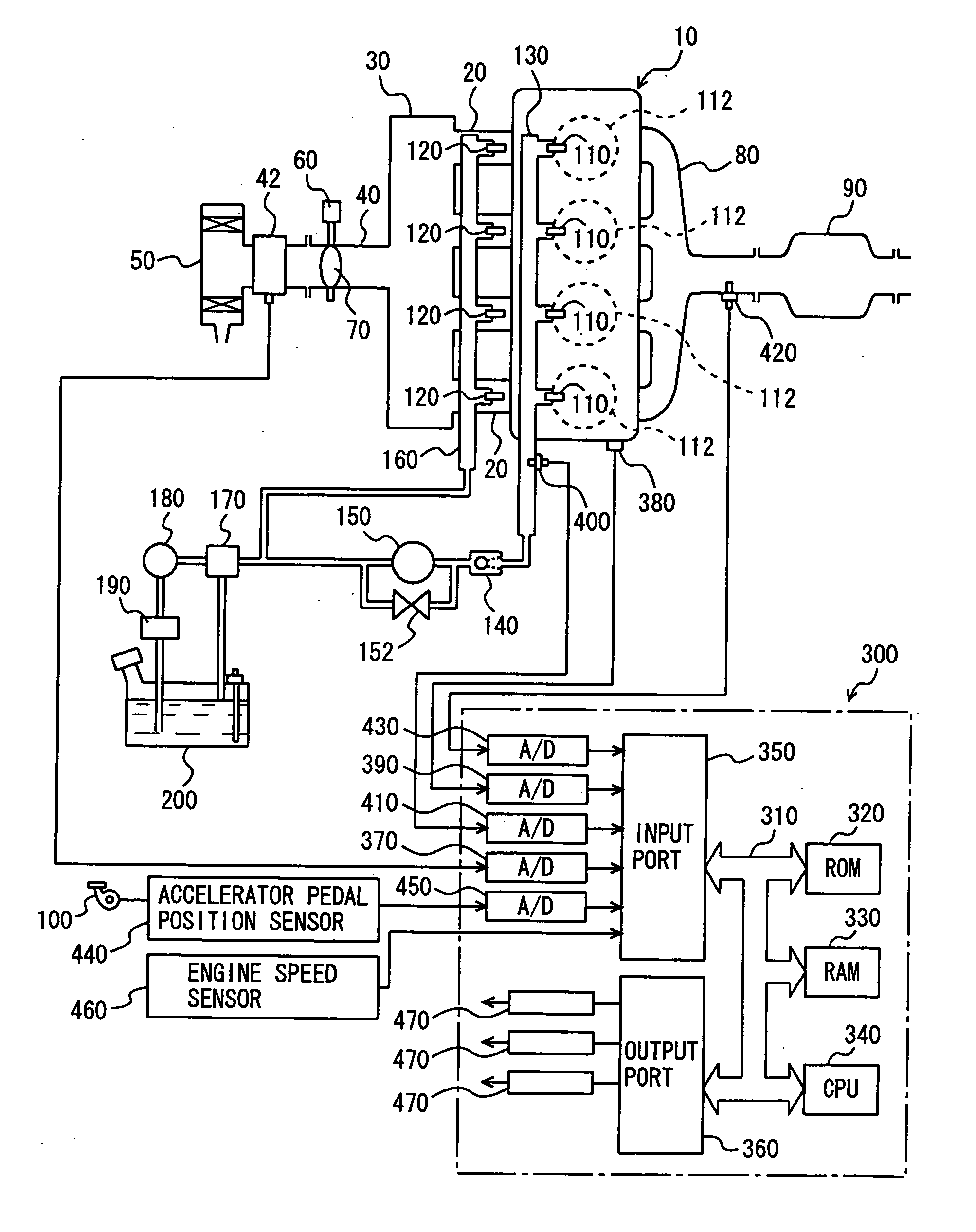
[0039]FIG. 1 is a schematic configuration diagram of an engine system that is controlled by an engine ECU (Electronic Control Unit) implementing the control apparatus for an internal combustion engine according to an embodiment of the present invention. In FIG. 1, an in-line 4-cylinder gasoline engine is shown, although the application of the present invention is not restricted to such an engine.

[0040] As shown in FIG. 1, engine 10 includes four cylinders 112, each connected via a corresponding intake manifold 20 to a common surge tank 30. Surge tank 30 is connected via an intake duct 40 to an air cleaner 50. An airflow meter 42 is arranged in intake duct 40, and a throttle valve 70 driven by an electric motor 60 is also arranged in intake duct 40. Throttle valve 70 has its degree of opening controlled based on an output signal of an engine ECU 300, independently from an accelerator pedal 100. Each cylinder 112 is connected to a common exhaust manifold 80, which is connected to a t...

second embodiment

[0062] In the following, an engine system controlled by an engine ECU implementing a control apparatus for an internal combustion engine of the present embodiment will now be described. In the present embodiment, description of a structure that is the same as in the above-described first embodiment will not be repeated. For example, a schematic structure of the engine system in the present embodiment is the same as that of the engine system shown in FIG. 1. In the present embodiment, a program that is different from the program executed by engine ECU 300 in the above-described first embodiment will be executed.

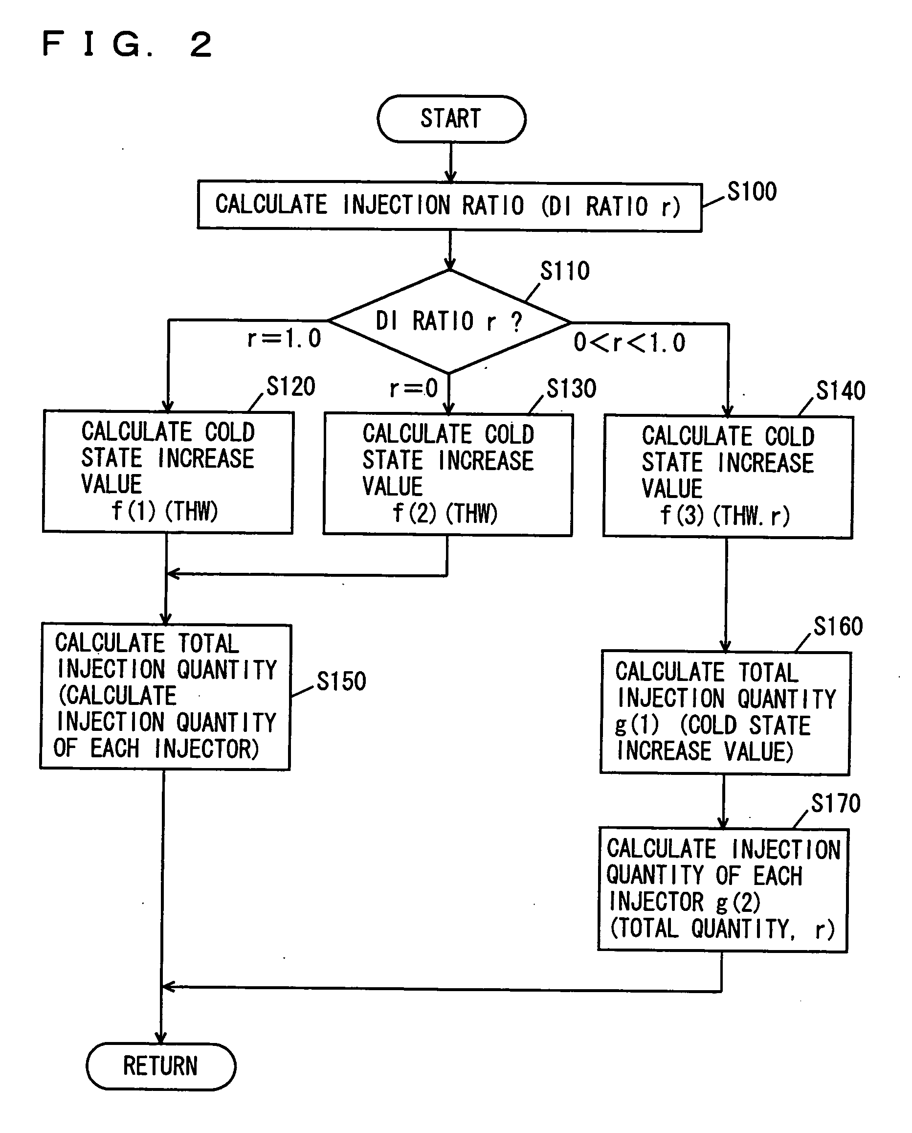
[0063] Referring to the flowchart of FIG. 4, a control structure of the program executed at engine ECU 300 is now described. In the flowchart of FIG. 4, process steps that are the same as in the flowchart of FIG. 2 have the same step number allotted. The processes are also the same. Thus, detailed description thereof will not be repeated here.

[0064] In S200, engine ECU 300 c...


PUM


Abstract

An engine ECU executes a program including the steps of calculating an in-cylinder injector's injection ratio; if the ratio is 1, calculating a cold state increase value by employing a function f(1) having the engine's temperature as a parameter; if the ratio is 0, calculating a cold state increase value by employing a function f(2) having the engine's temperature as a parameter; and if the ratio is larger than 0 and smaller than 1, calculating a cold state increase value by employing a function f(3) having the engine's temperature and the ratio as parameters.

Description

[0001] This nonprovisional application is based on Japanese Patent Application No. 2004-328111 filed with the Japan Patent Office on Nov. 11, 2004, the entire contents of which are hereby incorporated by reference. BACKGROUND OF THE INVENTION [0002] 1. Field of the Invention [0003] The present invention relates to a control apparatus for an internal combustion engine having a first fuel injection mechanism (an in-cylinder injector) injecting fuel into a cylinder and a second fuel injection mechanism (an intake manifold injector) injecting the fuel into an intake manifold or an intake port, and particularly, to a technique wherein a fuel injection ratio between the first and second fuel injection mechanisms are considered to determine a fuel increase value in a cold state operation. [0004] 2. Description of the Background Art [0005] An internal combustion engine having an intake manifold injector for injecting fuel into an intake manifold of the engine and an in-cylinder injector for...

Claims


Application Information

Patent Timeline
IPC IPC(8): F02B7/00F02M51/00
CPCF01N3/28F02D41/30F02D41/3094F02D41/38F02M63/0225F02M63/029F02M69/046F02M69/462F02M69/465F02M69/00
Inventor ARAKI, KOJI
Owner TOYOTA JIDOSHA KK
Features
  • Generate Ideas
  • Intellectual Property
  • Life Sciences
  • Materials
  • Tech Scout
  • Unparalleled Data Quality
  • Higher Quality Content
  • 60% Fewer Hallucinations
Learn More