
Electrocoagulation system

a technology of electrocoagulation system and coagulation chamber, which is applied in the direction of electrical-based machining apparatus, water treatment parameter control, water/sludge/sewage treatment, etc., can solve the problems of high cost associated with designing a system for each specific application, and achieve the effect of facilitating the treatment of various liquids or species

Inactive Publication Date: 2006-05-11
AQUENOX
View PDF13 Cites 36 Cited by
  • Summary
  • Abstract
  • Description
  • Claims
  • Application Information

AI Technical Summary

Benefits of technology

[0011] It is a further object of the invention to provide an improved control assembly for an electrocoagulation cell that facilitates treatment of various liquids or species. SUMMARY OF THE INVENTION

Problems solved by technology

A major drawback of the above systems is they are designed for a specific electrolyte or liquid which is to be treated.
A further drawback of conventional electrocoagulation systems is the high cost associated with designing a system for each specific application.

Method used


Image

  • Electrocoagulation system
  • Electrocoagulation system
  • Electrocoagulation system

Examples


Embodiment Construction

[0043] In a preferred form, the invention will be described with reference to an electrocoagulation cell and system of the type described in the co-pending International Patent Application No. PCT / AU01 / 00054. However, it should be noted that the invention could also be realised with other types of electrocoagulation cells.

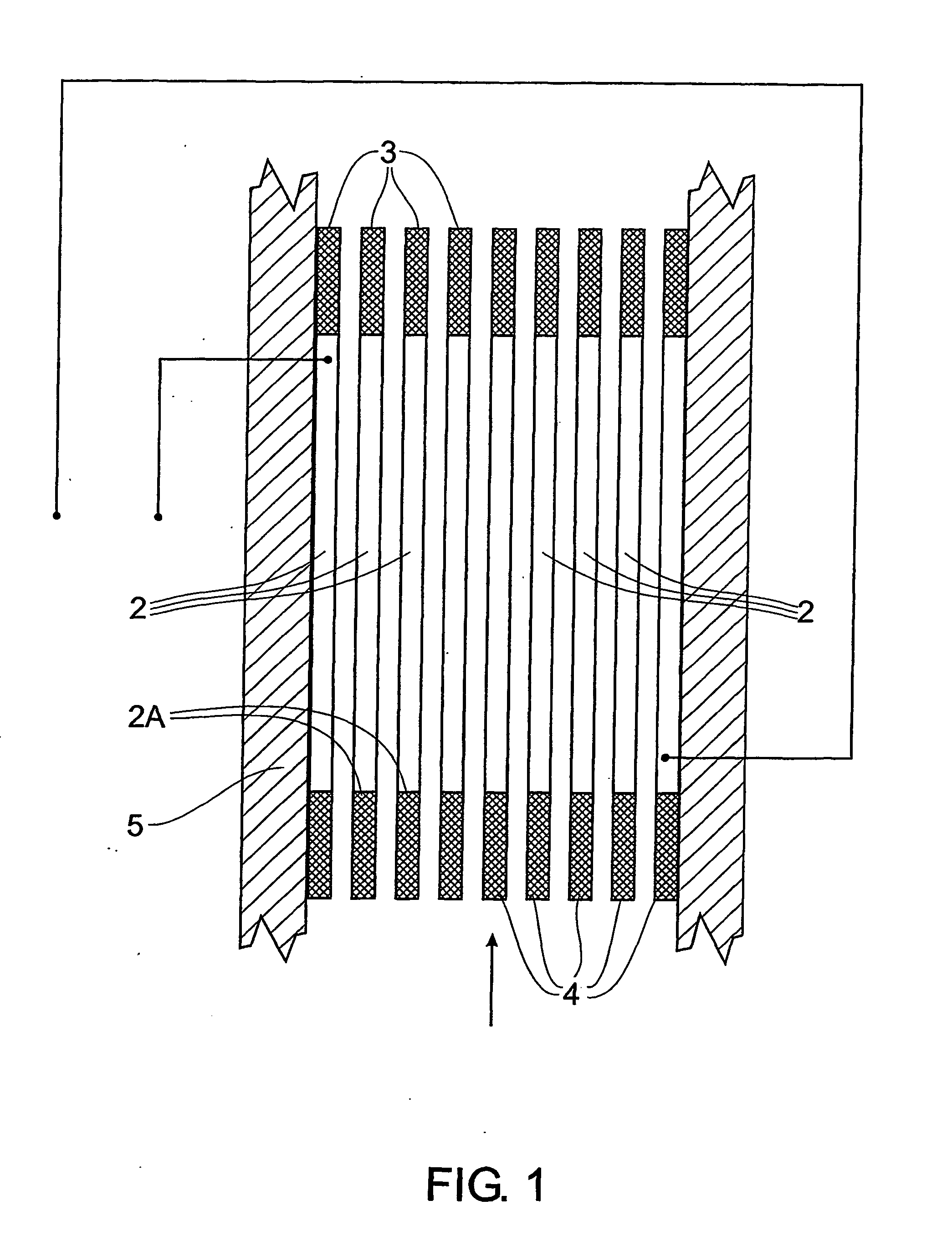
[0044] Referring now to FIG. 1, there is generally shown an electrocoagulation cell 1 comprising a plurality of electrodes 2, in the form of plates, which form the electrocoagulation cell. Plate extensions 3 and 4 abut the respective edges 2A of the electrodes 2 which form part of a housing 5 of the electrocoagulation cell 1. The extensions 3 and 4 prevent short-circuiting between the electrodes 2 of different potential. DC power to the electrocoagulation cell is applied to the two end electrodes as shown in FIG. 1.

[0045] The electrocoagulation cell is used in fluid treatment plants for treatment and purification of a conductive solution such as might be produced...


PUM

PropertyMeasurementUnit
Currentaaaaaaaaaa
Currentaaaaaaaaaa
Temperatureaaaaaaaaaa

Abstract

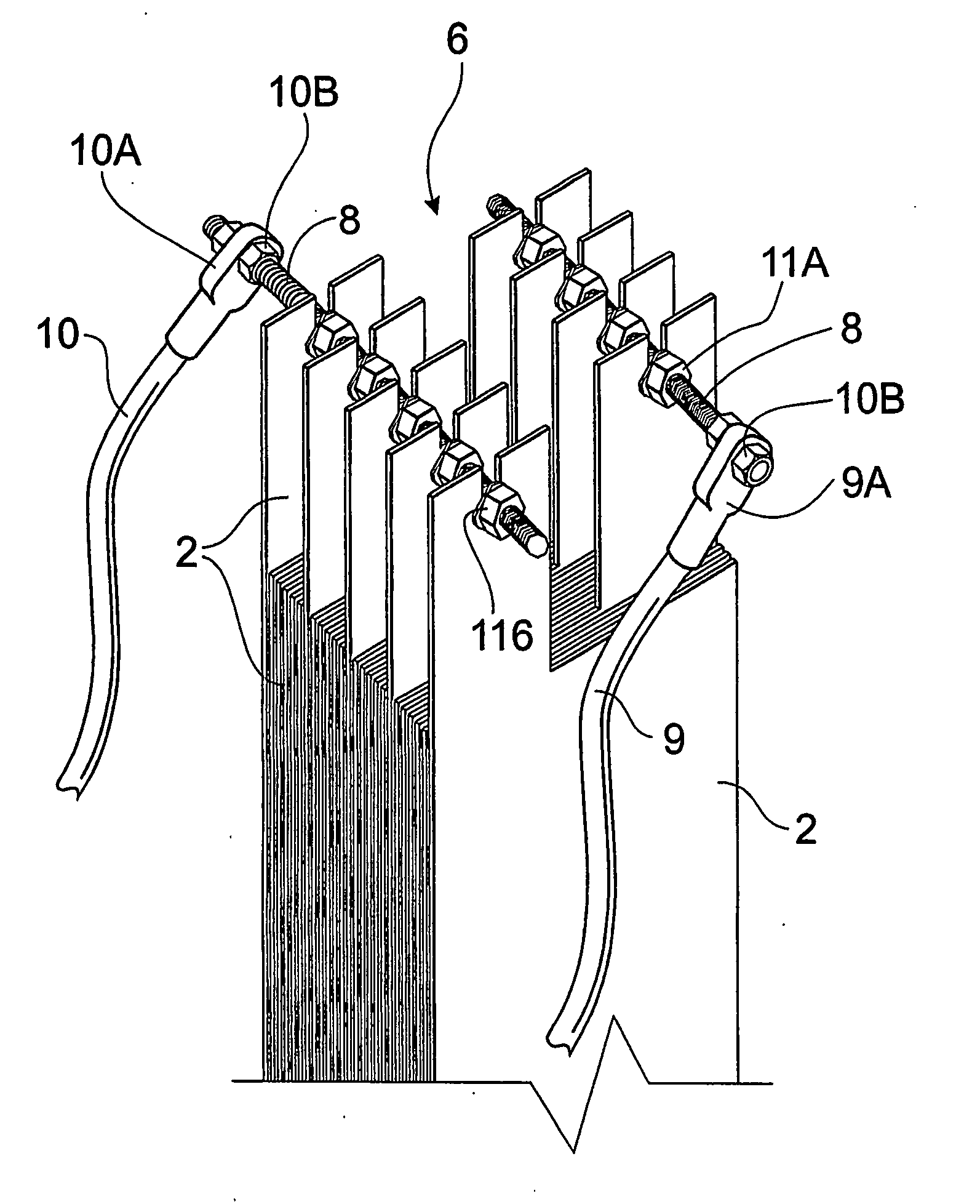
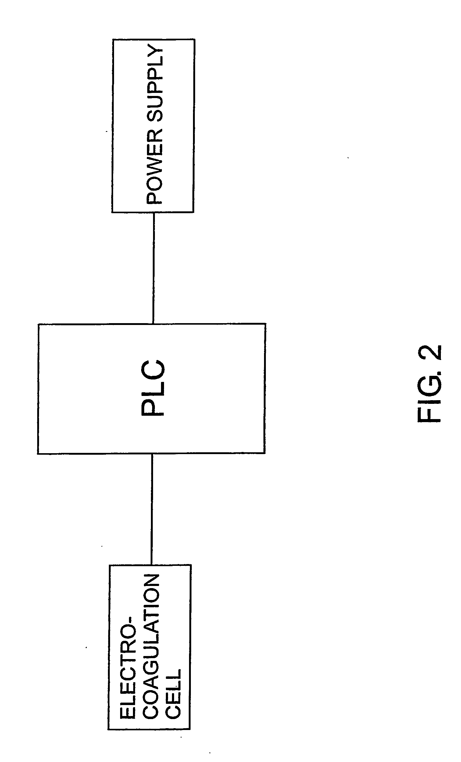
A control assembly for an electrocoagulation cell (1) comprising a plurality of electrodes, a releasable connection means (6) between at least a selection of the electrodes and electrical connection means (9, 10, 9A, 10A) attached to the releasable connection means (6) which in use is connectable to a power supply (12). An electrocoagulation system comprising a plurality of electrodes (2), an electrolytic cell (1) having an internal chamber which contains the plurality of electrodes (2), and a power supply (12) connectable to a power source and also connectable to the electrodes said power supply having control means (14, 24) for providing a selected constant output current or selected constant output voltage whereby the electrolytic cell may process samples of varying characteristics.

Description

TECHNICAL FIELD OF THE INVENTION [0001] This invention relates to an electrocoagulation system which an electrocoagulation cell includes as well as a control assembly for an electrocoagulation cell. BACKGROUND OF THE INVENTION [0002] Electrolytic cells are commonly used for treating liquids to change the liquid for a predetermined purpose. Electrocoagulation is a particular electrolytic treatment process for separating and removing contaminants or undesirable contents from a liquid. [0003] Typically an electrocoagulation cell contains electrodes and an electrolyte that is to be treated. The treatment process may be performed in a number of ways depending on the nature of the electrolyte. [0004] Numerous prior patents describe electrocoagulation systems of which AU 707432 describes an electrochemical treatment device for softening water. The device is powered by a current generator producing a current which is adjustable and applied to an anode and cathode terminal of an electrolytic...

Claims


Application Information

Patent Timeline
IPC IPC(8): C25B9/04C02F1/00C02F1/38C02F1/461C02F1/463C02F1/66C02F9/00
CPCC02F1/38C02F1/46109C02F1/463C02F1/66C02F9/00C02F2001/46128C02F2001/46133C02F2101/006C02F2201/46125C02F2201/46145C02F2209/001C02F2209/05C02F2209/06
Inventor KING, CAMERON JAMES
Owner AQUENOX
Learn More