Method and system for a single-fed patch antenna having improved axial ratio performance

a single-fed patch antenna and axial ratio technology, applied in the field of patch antennas, can solve the problems of insufficient or affordable current physical layer supporting conventional communications networks, inability to adapt to movable bodies, and inability to meet the needs of airborne platforms used in military communications, etc., to achieve the effect of reducing the cost, and improving the axial ratio performan

Inactive Publication Date: 2006-05-11
MITRE SPORTS INT LTD
View PDF5 Cites 19 Cited by
  • Summary
  • Abstract
  • Description
  • Claims
  • Application Information

AI Technical Summary

Benefits of technology

[0015] Consistent with the principles of the present invention as embodied and broadly described herein, a micro-strip antenna includes a conducting ground plane and a dielectric substrate mounted above the conducting ground plane. Also included is a patch element mounted above the dielectric substrate and configured to produce an antenna pattern. The antenna pattern is formed by a number of linear polarization components. The patch element includes a single feed point extending through the conducting ground plane and the dielectric substrate. Two or more notches within the patch element are configured to perturb each of the linear polarization components.

Problems solved by technology

The current physical layer supporting conventional communications networks, however, is not adequate or affordable for airborne platforms used in military communications.
Cost factors have previously made this multi-beam technology largely unaffordable.
However, with new emerging technologies in phased array antennas, there is a tremendous potential to lower the cost.
Another key performance parameter, axial ratio, can be viewed as a measure of circular polarization purity (roundness).One challenge with using conventional micro-strip patch antennas in satellite communications is achieving acceptable axial ratio values over the required bandwidth.
These multiple feed arrangements, however, translate into additional power consumption and costs.
Unfortunately, these conventional configurations perform well only across very narrow bands .
This narrow bandwidth performance limits use of these traditional techniques within the broadband and high speed data environments characteristic of robust air and ground communication networks of today and in the future.

Method used


Image

  • Method and system for a single-fed patch antenna having improved axial ratio performance
  • Method and system for a single-fed patch antenna having improved axial ratio performance
  • Method and system for a single-fed patch antenna having improved axial ratio performance

Examples


Embodiment Construction

[0028] The following detailed description of the present invention refers to the accompanying drawings that illustrate exemplary embodiments consistent with this invention. Other embodiments are possible, and modifications may be made to the embodiments within the spirit and scope of the invention. Therefore, the detailed description is not meant to limit the invention. Rather, the scope of the invention is defined by the appended claims.

[0029] The present invention, as described below, may be implemented in many different embodiments of software, hardware, firmware, and / or the entities illustrated in the figures. Any actual software code with the specialized control of hardware to implement the present invention is not limiting of the present invention. Thus, the operational behavior of the present invention will be described with the understanding that modifications and variations of the embodiments are possible, given the level of detail presented herein.

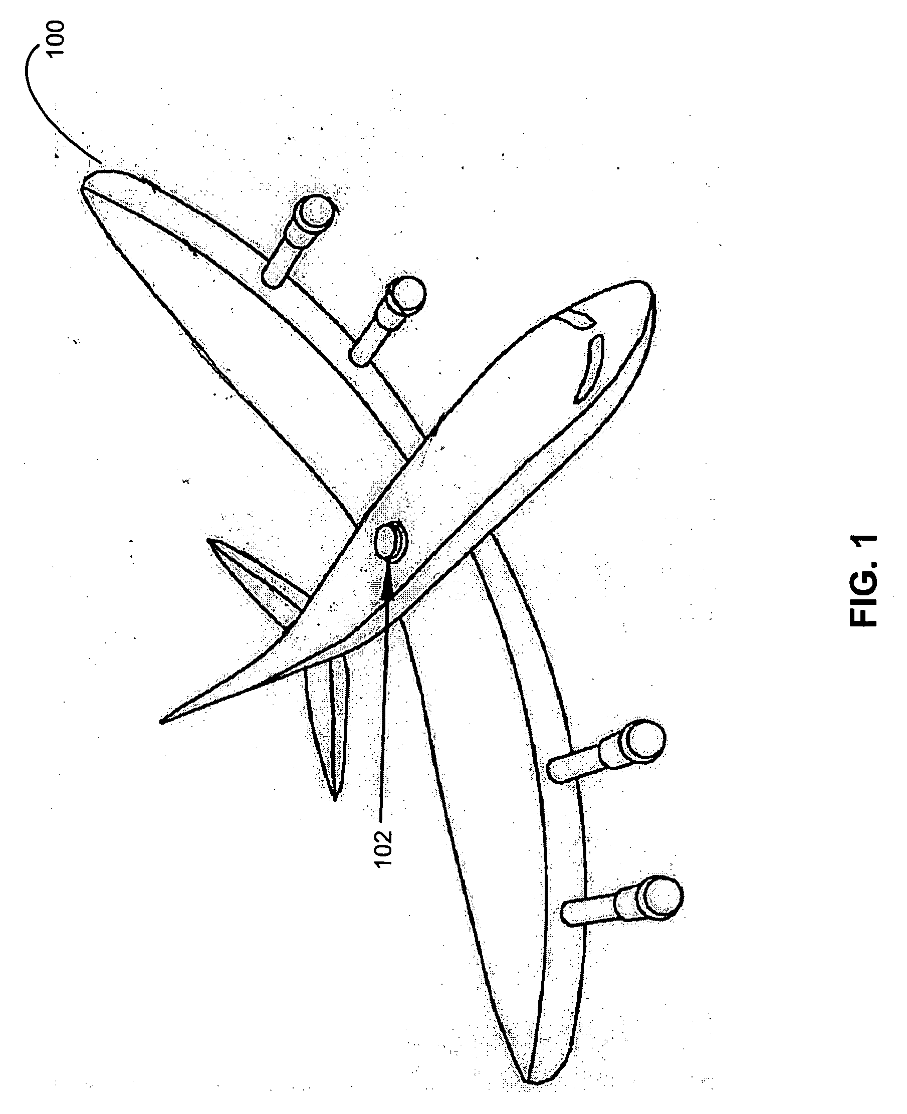
[0030]FIG. 1 is an illu...


PUM


Abstract

A micro-strip antenna includes a conducting ground plane and a dielectric substrate mounted above the conducting ground plane. A patch element is mounted above the dielectric substrate and configured to produce an antenna pattern. The antenna pattern is formed by a number of linear polarization components. The patch element includes a single feed point extending through the conducting ground plane and the dielectric substrate. Two or more notches within the patch element are configured to perturb each of the linear polarization components.

Description

STATEMENT REGARDING FEDERALLY-SPONSORED RESEARCH AND DEVELOPMENT [0001] Part of the work performed during development of this invention utilized U.S. Government funds. The U.S. Government has certain rights in this invention.BACKGROUND OF THE INVENTION [0002] 1. Field of the Invention [0003] The present invention relates generally to the field of patch antennas. [0004] More specifically, the present invention relates to deriving dual-band performance characteristics from a micro-strip patch antenna. [0005] 2. Background Art [0006] A transformation to information driven network centric warfare has been receiving much attention of late. Connectivity between systems and platforms is required to achieve the goals of this transformation. The air and ground communications networks supporting this connectivity require survivable and secure free space optical and radio frequency (RF) links. [0007] A component critical to network operations and connectivity, is the physical layer. The curren...

Claims


Application Information

Patent Timeline
Patent Type & Authority Applications(United States)
IPC IPC(8): H01Q1/38
CPCH01Q9/0428H01Q9/0478
Inventor MAHMOUD, MOHAMED S.
Owner MITRE SPORTS INT LTD
Why Eureka
Try Eureka