Circular polarized antenna with omnidirectional broad axial ratio beam width

A technology of circularly polarized antenna and beam width, which is applied in the direction of antenna, antenna grounding device, radiating element structure, etc. It can solve the problems of unfavorable low profile design, unfavorable antenna miniaturization, and high height of helical antenna, so as to improve the axial ratio beam The effect of width, light weight and low profile

Inactive Publication Date: 2012-06-20
SHANGHAI JIAO TONG UNIV
View PDF4 Cites 16 Cited by
  • Summary
  • Abstract
  • Description
  • Claims
  • Application Information

AI Technical Summary

Problems solved by technology

[0004] After searching the existing technical literature, it was found that Sun Xiangzhen published "Research on Circularly Polarized Double-layer Microstrip Antenna" in "Remote Measurement and Remote Control" Issue 05, 2004. This article introduced the structure of a double-layer circularly polarized microstrip antenna. For the basic double-feed point microstrip structure, although its axial ratio beam width (<3dB) is -67°~60° on the plane of phi=0, it is only -67 on the plane of vertical plane phi=90 °~14°. In addition, this document improves the axial ratio beam width of the antenna by cutting angles and four-point feeding method. The four-point feeding method makes the axial ratio beam width reach ±60°, but the four-point feeding method It leads to a complex feed network, which is not conducive to the miniaturization of the antenna
Although the angle-cutting method improves the overall axial ratio of the antenna, the axial ratio beam width of less than 3dB is still less than 40° on some surfaces
"Development of a Wide-beam Circularly Polarized Antenna" published by Han Yingchen and others in the "Journal of Missile and Guidance" No. 3 in June 2009. This article introduces a microstrip four-wall helical antenna. The antenna Although the circular polarization axis ratio is less than 3dB in the range of ±50°, the height of the helical antenna is too high, which is not conducive to the low profile design requirements

Method used


Image

  • Circular polarized antenna with omnidirectional broad axial ratio beam width
  • Circular polarized antenna with omnidirectional broad axial ratio beam width
  • Circular polarized antenna with omnidirectional broad axial ratio beam width

Examples


Embodiment Construction

[0033] The present invention is described in detail below in conjunction with accompanying drawing and embodiment: present embodiment is implemented under the premise of technical solution of the present invention, has provided detailed embodiment and specific operation process, but protection scope of the present invention is not limited to the following the described embodiment.

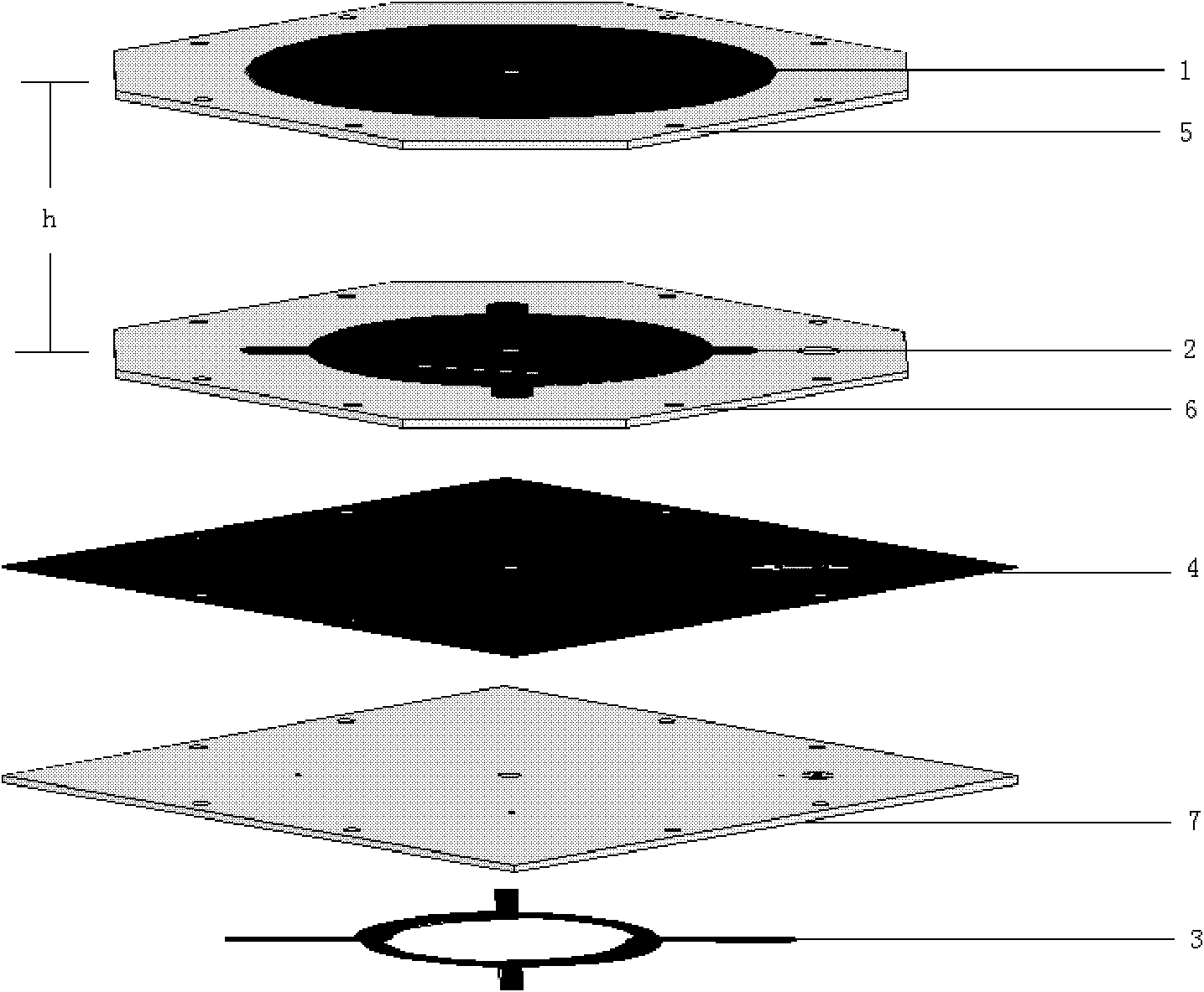
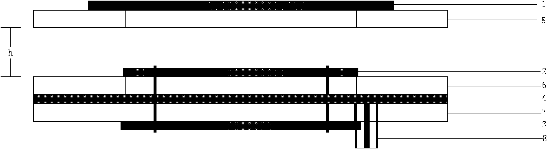
[0034] Please see first figure 1 and figure 2 , figure 1 It is a schematic diagram of a three-dimensional layered structure of a circularly polarized microstrip patch antenna with a wide-axis ratio beamwidth according to the present invention, figure 2 It is a schematic diagram of the side structure of the circularly polarized microstrip patch antenna with wide-axis ratio beam width of the present invention. As shown in the figure, a circularly polarized antenna with an omnidirectional wide-axis ratio beam width includes, from top to bottom: a parasitic unit 1, an upper dielectric substrate 5,...


PUM


Abstract

The invention discloses a circular polarized antenna with omnidirectional broad axial ratio beam width. The circular polarized antenna comprises a parasitic element, an upper-layer medium baseplate, an exciting element, a middle-layer medium baseplate, an earthing unit, a lower-layer medium baseplate and a 3dB mixed electric bridge electric feeding network, wherein the parasitic element and the exciting element are respectively arranged on the upper surfaces of the upper-layer medium baseplate and the middle-layer medium baseplate; the upper-layer medium baseplate and the middle-layer medium baseplate are separated by an air layer; the 3dB mixed electric bridge electric feeding network is placed on the lower surface of the lower-layer medium baseplate; an internal conductor of a coaxial electric feeding unit is connected with an input port of the 3dB electric bridge electric feeding network; and an external conductor of the coaxial electric feeding unit penetrates through the lower-layer medium baseplate and is connected with the earthing unit. According to the invention, not only is the circular polarized radiation realized very well, at the same time, the circular polarized antenna has broader axial ratio beam width within the omnidirectional range, is small in volume, is low in section plane, is light in weight, is simple in structure, and is easy to be conformal.

Description

technical field [0001] The invention relates to the field of circularly polarized antennas, in particular to a circularly polarized microstrip patch antenna with a wide axial ratio beam width. Background technique [0002] With the development of satellite communication, launch vehicle measurement and control communication technology, the expansion of radar application range and the need to track and measure high-speed targets under various polarization modes and weather conditions, it is difficult for a single polarization mode to meet the requirements. Circularly polarized antennas application becomes very important. In electronic countermeasures, circularly polarized antennas can be used to interfere and detect enemy radio waves of various linear polarization and elliptical polarization. Installing circularly polarized antennas on violently swinging or rolling aircraft can reduce signal loss. In addition, it can also eliminate the distortion effect caused by the ionosphe...

Claims


Application Information

Patent Timeline
Patent Type & Authority Applications(China)
IPC IPC(8): H01Q1/38H01Q1/48H01Q13/08
Inventor 闫鹏金荣洪耿军平粱仙灵李振海白旭东李文晶
Owner SHANGHAI JIAO TONG UNIV
Why Eureka
Try Eureka