
Compact type broadband bicircular polarization patch antenna based on coupling microstrip line coupler

A coupler and microstrip line technology, applied in the field of compact broadband dual circularly polarized patch antennas based on coupled microstrip line couplers, can solve the unfavorable research and reports of compact broadband dual circularly polarized antennas. Low cost, miniaturization, and insufficiently compact structure of the antenna, to achieve the effect of compact structure, small occupied circuit area, and reduced volume

Active Publication Date: 2013-08-14
北京神州腾耀通信技术有限公司
View PDF5 Cites 18 Cited by
  • Summary
  • Abstract
  • Description
  • Claims
  • Application Information

AI Technical Summary

Problems solved by technology

Now, the 3dB branch line coupler is often used as the power distribution and phase-shifting feed network of dual-feed dual circularly polarized antennas, but this structure has some shortcomings: first, because of its structure is not compact enough, the circuit The large area is not conducive to the low cost and miniaturization of the antenna; in addition, the theoretical value of its 1dB amplitude imbalance relative bandwidth is 27%, and the phase imbalance relative bandwidth of (90±5) degrees is only 33%
However, so far, in the literature or papers published at home and abroad, no relevant research and reports on the compact broadband dual circularly polarized antenna based on the 3dB coupled microstrip line coupler have been found.

Method used


Image

  • Compact type broadband bicircular polarization patch antenna based on coupling microstrip line coupler
  • Compact type broadband bicircular polarization patch antenna based on coupling microstrip line coupler
  • Compact type broadband bicircular polarization patch antenna based on coupling microstrip line coupler

Examples


Embodiment Construction

[0018] In order to make the object, technical solution and advantages of the present invention clearer, the present invention will be further described in detail below in conjunction with the accompanying drawings and embodiments.

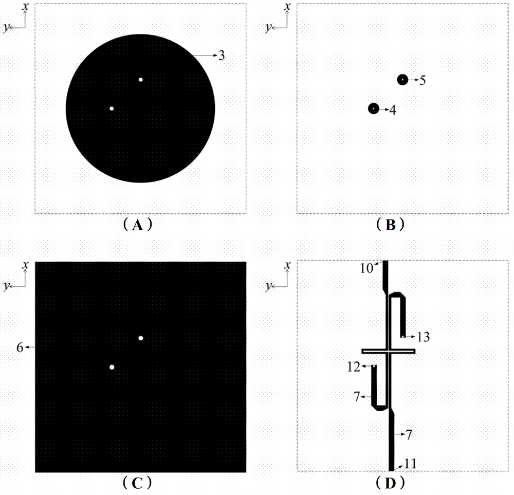
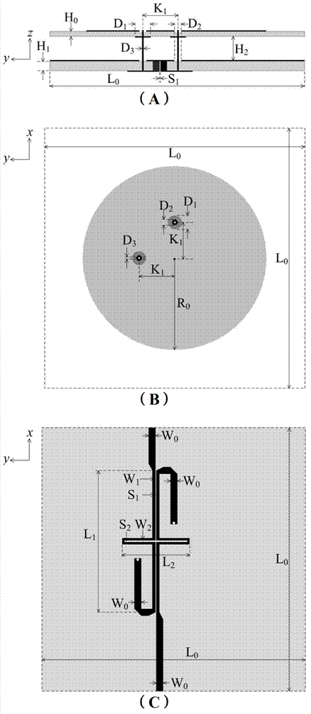
[0019] see figure 1 and figure 2 , introduce the side view of the structural composition of the antenna of the present invention and the schematic diagram of the circuit structure of each layer: the main radiation patch 3 is respectively arranged on the lower and upper surfaces of the two dielectric substrates 1 and 2 from top to bottom using printed circuit board technology (see figure 2 -A) and two capacitively coupled patches 4 and 5 (see figure 2 -B), ground plane 6 (see figure 2 -C) and feed network 7 (see figure 2 -D), the feed network 7 is a compact, broadband 3dB coupled microstrip line coupler used as a circularly polarized orthogonal feed network for power distribution and 90-degree phase shift. The two dielectric substrates 1 a...


PUM


Abstract

A compact type broadband bicircular polarization patch antenna based on a 3 dB coupling microstrip line coupler adopts a printed circuit board technology to arrange a feed network, a ground plane and capacitance coupling patches and a main radiation patch on the upper surfaces and the lower surfaces of two dielectric substrates from bottom to top, wherein the feed network is the 3 dB broadband coupling microstrip line coupler with a compact structure, so that the circular polarization orthogonal feed network with functions of power distribution and 90-degree phase shift is formed; and the two dielectric substrates are supported and fixed by upright columns and nuts made of a non-conducting material, and a gap is reserved between the two dielectric substrates to form air dielectrics. Two output ends of the feed network and the two capacitance coupling patches are connected together through two feed probes, and the orthogonal feed is performed on the main radiation patch through the mode of combining the metal probes and the capacitance coupling patches, and accordingly, circular polarization radiation with high gain, low axial ratio and broadband is achieved. The antenna achieves miniaturization of the broadband circular polarization patch, is simple in structure and low in cost, and facilitates popularization and application.

Description

technical field [0001] The present invention relates to a kind of wireless communication antenna, to be exact, relates to a kind of using 3dB coupled microstrip line coupler as compact power distribution and 90 degree phase-shifting quadrature feeding network, based on air medium and using feeding probe The method of combining with the capacitive patch feeds the circular main radiation patch to realize the compact broadband dual circularly polarized radiation antenna, which belongs to the technical field of the dual circularly polarized antenna. Background technique [0002] In recent years, with the rapid development and wide application of satellite navigation, communications and the Internet of Things, circularly polarized antennas are used as the front-end equipment of these systems. play an extremely important role. In addition, in order to facilitate the large-scale popularization and application of satellite communication terminals and radio frequency identification ...

Claims


Application Information

Patent Timeline
IPC IPC(8): H01Q1/38H01Q15/24H01Q1/50H01Q1/12
Inventor 吴永乐刘强苏明于翠屏黎淑兰刘元安
Owner 北京神州腾耀通信技术有限公司
Learn More