A design method for compact and lamination structure microstrip antenna integrated with the receiving and sending functions

A technology of laminated structure and design method, which is applied in the direction of antenna, radiating element structure, electrical components, etc., can solve the problem of low transmit-receive isolation of transceiver integrated antenna, low antenna gain of elevation angle and poor axial ratio performance, and is not suitable for portable terminals and other problems, to achieve the effect of minimizing the radiation area of ​​the antenna, improving the isolation of transceivers, and reducing the complexity of the structure

Inactive Publication Date: 2007-10-24
BEIHANG UNIV
View PDF0 Cites 16 Cited by
  • Summary
  • Abstract
  • Description
  • Claims
  • Application Information

AI Technical Summary

Problems solved by technology

First, the low-elevation gain and axial ratio performance of the antenna is poor. When there are few navigation satellites near the zenith angle, the antenna needs to have good low-elevation gain and axial ratio performance to receive

Method used


Image

  • A design method for compact and lamination structure microstrip antenna integrated with the receiving and sending functions
  • A design method for compact and lamination structure microstrip antenna integrated with the receiving and sending functions
  • A design method for compact and lamination structure microstrip antenna integrated with the receiving and sending functions

Examples


Embodiment Construction

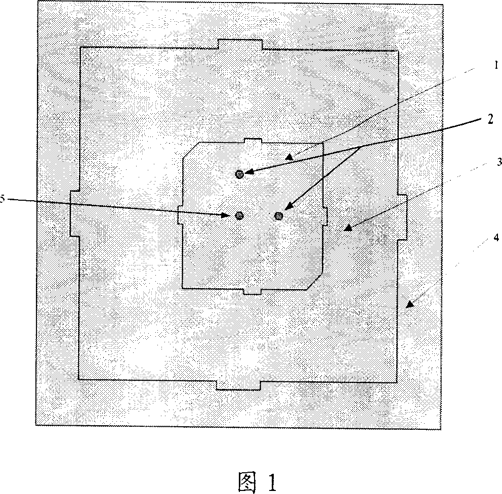
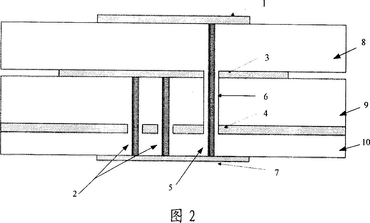
[0024] The structure of the antenna is shown in Figure 1 and Figure 2. The receiving antenna radiator 1 and the transmitting antenna radiator 3 are respectively located on the front surfaces of the dielectric substrate 8 and the dielectric substrate 9 . The signal received by the receiving antenna is fed to the feeding network through the feeding probe 5 . The signal emitted by the radiating antenna is fed from the feeding network to the radiator 3 of the radiating antenna via the feeding probe 2 .

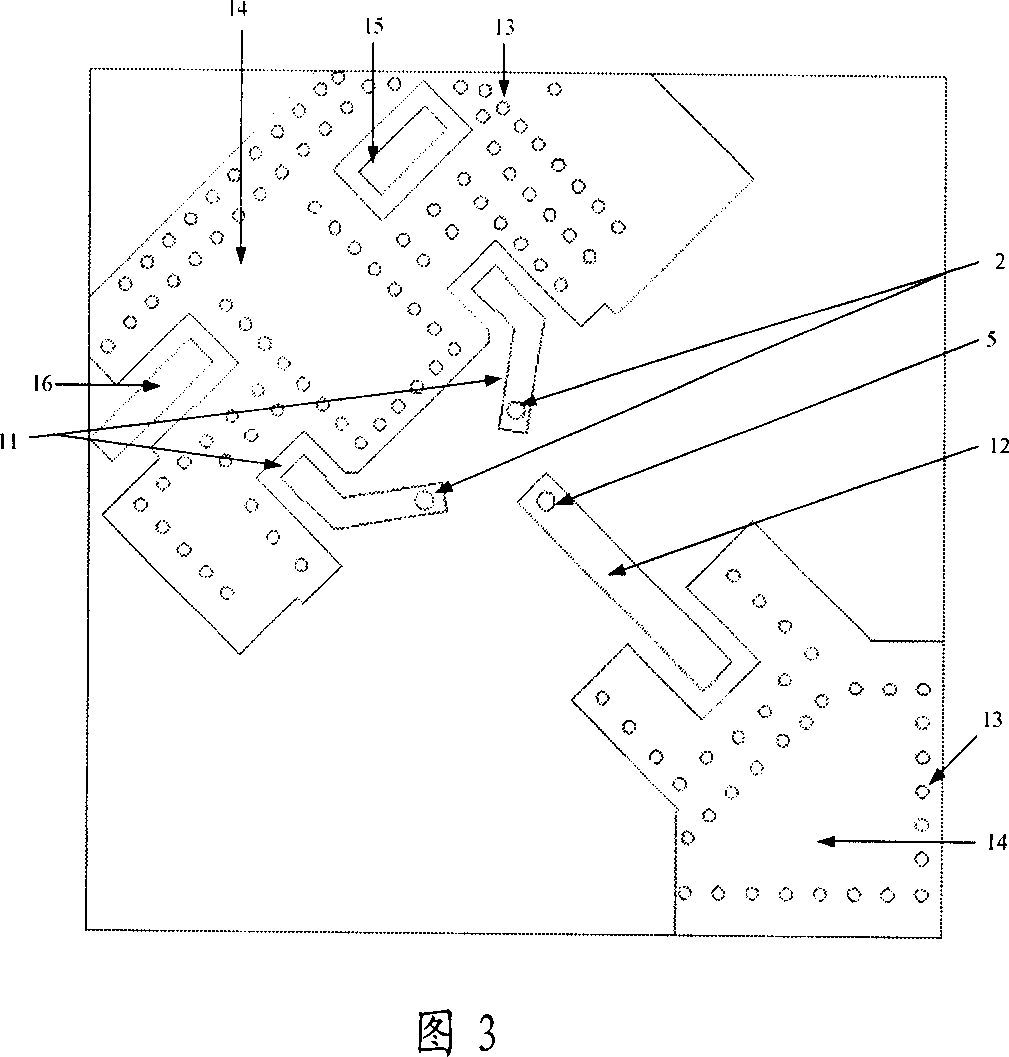
[0025] Figure 3 is a top view of the feed network. The 3dB coupler used in double-feed uses commercial chips.

[0026] Explanation of each label:

[0027] 1 receiving antenna; 2 transmitting antenna feeding probe; 3 transmitting antenna; 4 public floor; 5 receiving antenna feeding probe; 6 metallized through hole; 7 feeding network; 8 dielectric substrate; 9 dielectric substrate; 10 dielectric substrate ; 11 feed microstrip line; 12 feed microstrip line; 13 via hole; 14 ground;...


PUM


Abstract

The related design method for compact stack integrated microstrip antenna comprises: 1. modeling and simulating the entire structure to obtain the key performance parameter; 2. determining/adjusting the top antenna radiator and its feed part position according to real requirement, adding a compensation strip on the bottom antenna radiation strip, determining the exact size, and optimizing the axial ratio performance and angle of elevation gain; and 3. adding a metal base under the public ground.

Description

technical field [0001] The invention relates to a design method of a microstrip antenna integrated with compact structure and laminated structure for transmitting and receiving. Background technique [0002] The application of satellite navigation and positioning system has been very extensive. We use satellite navigation and positioning signals to carry out sea, air and land navigation, missile guidance, precise positioning of geodesy and engineering survey, time transfer and speed measurement, etc. The size of user terminal equipment for satellite navigation is getting smaller and smaller, requiring the antenna to be miniaturized. [0003] There are generally some problems in the actual design of the antennas used by satellite navigation terminals. First, the low-elevation gain and axial ratio performance of the antenna is poor. When there are few navigation satellites near the zenith angle, the antenna needs to have good low-elevation gain and axial ratio performance to ...

Claims


Application Information

Patent Timeline
IPC IPC(8): H01Q13/08H01Q1/38
Inventor 苗俊刚罗贤梁郝立强赵鑫刘东海白冰李凤琴
Owner BEIHANG UNIV
Why Eureka
Try Eureka