Leaky wave antenna with radiating structure including fractal loops

a technology of radiating structure and antenna, applied in the structure of radiating elements, resonant antennas, instruments, etc., can solve the problems of increasing impedance at the end of the arm, and achieve the effect of smooth current distribution across the antenna, increasing impedance, and opening the bandwidth for wide bandwidth performan

Active Publication Date: 2007-07-31
NOVATEL INC
View PDF7 Cites 16 Cited by
  • Summary
  • Abstract
  • Description
  • Claims
  • Application Information

AI Technical Summary

Benefits of technology

[0013]More specifically, the antenna is comprised of a non-conductive substantially planar printed circuit board (“PCB”) substrate having an upper surface, which is metallized. The radiating structure is etched into the metallized upper surface of the substrate. As noted, the radiating structure is a network of interconnected slots that are shaped such that they begin as spiral slots and flare at their respective ends into fractal loop configurations. The fractal loop configuration at the end of each slot is coupled to the fractal loop configuration of an adjacent slot. This radiating structure of interconnected apertures create many RF paths, to open the bandwidth for wide bandwidth performance.
[0014]The flare of the slot arms also results in increased impedance at the end of the arm. By increasing the impedance at the end of the arm, a previous impedance discontinuity that may have existed is reduced in magnitude, leading to a smoother current distribution across the antenna. This continuously varying slot width and the interconnections between adjacent slot arms further smoothes out amplitude and phase patterns in the azimuth plane of the antenna. The radiating structure also provides a common phase center for the frequency bands of interest.
[0015]A microstrip multiple turn spiral transmission line is disposed on a lower surface of the substrate. The spiral shape of the transmission line improves the bandwidth performance of the antenna and improves the antenna efficiency in that the spiral feed microstrip crosses each slot twice thus allowing for the energy from each slot to be collected twice. In accordance with one aspect of the invention, the spiral feed microstrip is a two turn spiral. The spiral shape of the microstrip feeding transmission line has a larger bandwidth compared to circular feeding structures.

Problems solved by technology

The flare of the slot arms also results in increased impedance at the end of the arm.

Method used


Image

  • Leaky wave antenna with radiating structure including fractal loops
  • Leaky wave antenna with radiating structure including fractal loops
  • Leaky wave antenna with radiating structure including fractal loops

Examples


Embodiment Construction

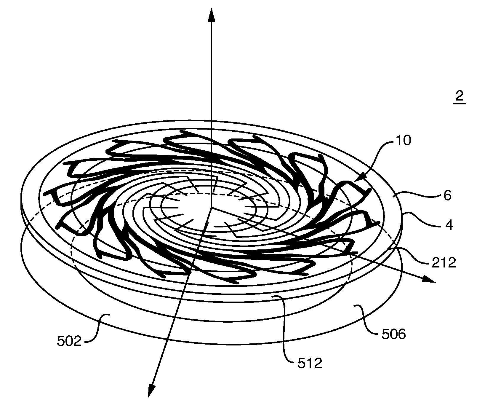
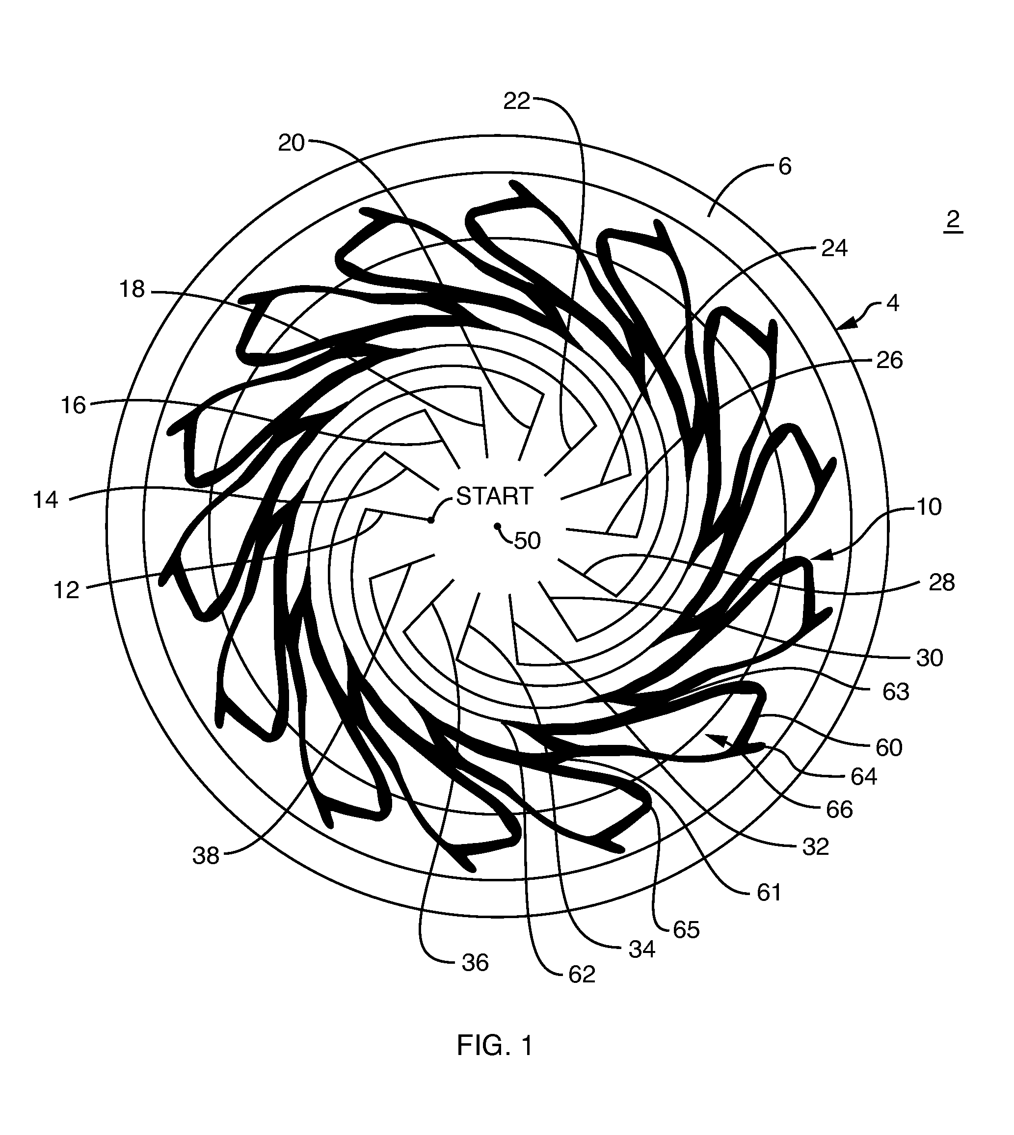
[0032]FIG. 1 is a diagrammatical view of the antenna 2 of the present invention illustrating the substrate 4 which is made of a PCB material. The upper surface 6 of the substrate 4 is metallized or plated. A radiating slot structure 10 is etched into the metallized upper surface 6, using standard PCB techniques. In accordance with the invention, the radiating slot structure 10 is a multi-armed aperture-coupled network with N spiral slot arms in a self-complementary structure, with each slot arm terminating in a fractal slot geometric shape. This creates a fixed beam phased array of aperture-coupled slots optimized to receive a right hand polarized signal.

[0033]More specifically, the radiating slot structure 10 includes a plurality of spiral slot arms 12 through 38. In the illustrative embodiment of FIG. 1, there are fourteen spiral slot arms. However, in other applications of the invention, the radiating slot structure may contain a different number of spiral slot arms or may contai...


PUM


Abstract

An antenna is provided for acquiring RF signals from various satellite ranging systems including GPS, GLONASS, GALILEO and OmniSTAR®. The antenna configuration includes a radiating structure of multi-arm spiral slots terminated with fractal loops. A leaky wave microstrip spiral feed network is used to excite the radiating structure of the antenna. The fixed beam phased array of aperture coupled slots is optimized to receive a right hand polarized signal. The proposed antenna is made out of a single PCB board. The antenna has a very uniform phase and amplitude pattern in the azimuth plane from 1.15 to 1.65 GHz, therefore providing consistent performance at GPS, GLONASS, GALILEO and OmniSTAR® frequencies. The antenna also has a common phase center at the various frequencies from 1175 MHz to 1610 MHz and substantially the same radiation pattern and axial ratio characteristics.

Description

BACKGROUND OF THE INVENTION[0001]1. Field of the Invention[0002]The present invention is related to planar spiral slot antennas and, more particularly, to such antennas having a wide bandwidth.[0003]2. Background Information[0004]Antenna design requirements differ depending upon the particular application of the antenna. Recently, there is a demand for antennas which have the capability of acquiring RF signals from various satellite ranging systems. For example, the satellite ranging systems include the United States Global Positioning System (GPS), the Russian Federation GLONASS System, the European GALILEO System, and commercial services such as the OmniSTAR® System, which provides GPS enhancement data via satellite.[0005]The various satellite ranging systems use signals in different frequency bands, which range from 1175 MHz to 1610 MHz. Thus, a wide bandwidth is required for an antenna designed to receive signals from different ranging systems, and in particular for an antenna d...

Claims


Application Information

Patent Timeline
Patent Type & Authority Patents(United States)
IPC IPC(8): H01Q13/10H01Q1/36H01Q1/38G01S19/44G01S19/46
CPCH01Q1/36H01Q9/27H01Q13/20
Inventor KUNYSZ, WALDEMARBADGER, EARLPLAMONDON, DAVID
Owner NOVATEL INC
Why Eureka
Try Eureka