Resonator system with a plurality of individual mechanically coupled resonators and method of making same

a mechanical coupling and resonator technology, applied in piezoelectric/electrostrictive/magnetostrictive devices, piezoelectric/electrostriction/magnetostriction machines, electrical apparatus, etc., can solve the problem of requiring too high a voltage for operation, unable to achieve a sufficiently high quality (o) level with a 50 load, and traditional resonators are too large to incorporate one or more resonators onto an integrated circui

Active Publication Date: 2005-06-30
CHARLES STARK DRAPER LABORATORY
View PDF14 Cites 31 Cited by
  • Summary
  • Abstract
  • Description
  • Claims
  • Application Information

AI Technical Summary

Benefits of technology

[0020] It is a further object of this invention to provide such a system which avoids the need for sub-micron gaps and large actuation voltages.
[0021] It is a further obj

Problems solved by technology

For example, many are too large for placement onto an integrated circuit, operate in an unsatisfactorily small frequency range, require too high a voltage for operation, and/or cannot achieve a sufficiently high Quality (O) level with a 50 Ω load.
Many traditional resonators are too large to incorporate one or more resonators onto an integrated circuit.
Several traditional resonators operate in an undesirably limited frequency range.
MEMS flexural mode beam resonators typically do not operate satisfactorily in the Ultra-High Frequency range.
Similarly, TFBARs and SMRs are difficult to make with center frequencies much below 1 GHz since film stress becomes an issue as the film thickness is increased.
Furthermore, with most film based resonators, multiple resonators with differing frequencies cannot be placed on a single integrated circuit because the film thickness is typically uniform across a substrate.
Many MEMS flexural mode beam resona

Method used


Image

  • Resonator system with a plurality of individual mechanically coupled resonators and method of making same
  • Resonator system with a plurality of individual mechanically coupled resonators and method of making same
  • Resonator system with a plurality of individual mechanically coupled resonators and method of making same

Examples


Embodiment Construction

[0054] Aside from the preferred embodiment or embodiments disclosed below, this invention is capable of other embodiments and of being practiced or being carried out in various ways. Thus, it is to be understood that the invention is not limited in its application to the details of construction and the arrangements of components set forth in the following description or illustrated in the drawings. If only one embodiment is described herein, the claims hereof are not to be limited to that embodiment. Moreover, the claims hereof are not to be read restrictively unless there is clear and convincing evidence manifesting a certain exclusion, restriction, or disclaimer.

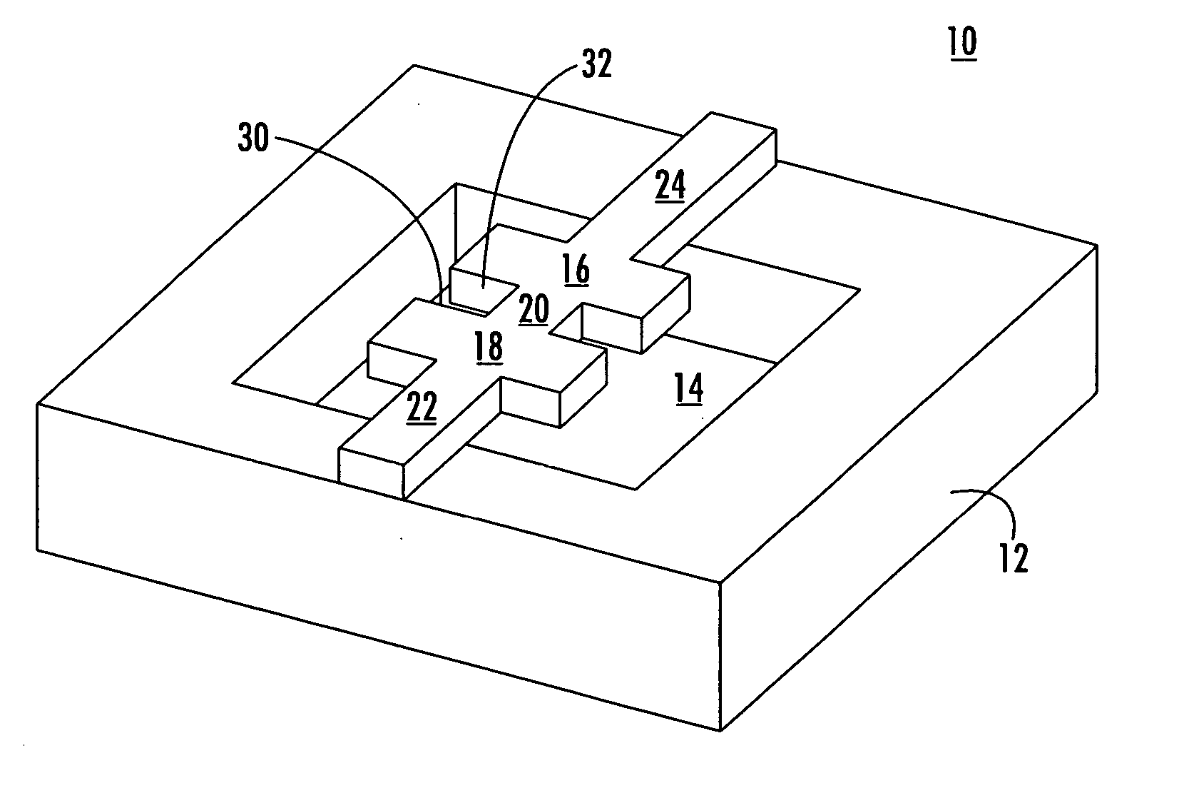
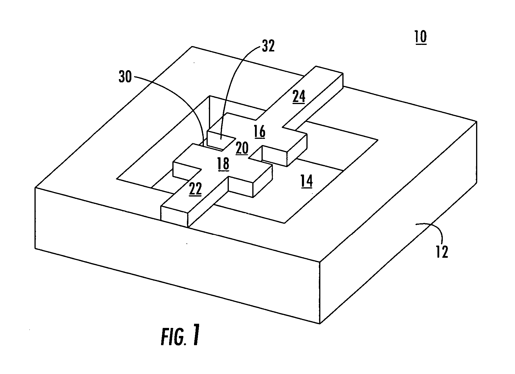
[0055] In one embodiment of the subject invention, dual resonator system 10, FIG. 1 includes silicon, silicon germanium, gallium arsenide, or glass substrate 12 with cavity 14 over which are suspended resonators 16 and 18 via supports 22 and 24. If there are more than two resonators, supports 22 and 24 are typically edge ...


PUM

PropertyMeasurementUnit
Flexibilityaaaaaaaaaa
Shapeaaaaaaaaaa
Frequencyaaaaaaaaaa

Abstract

A resonator system wherein a plurality of resonators each including piezoelectric material are suspended relative to a substrate. An edge of each resonator is mechanically coupled to an edge of another resonator and the plurality of resonators expand and contract reaching resonance in response to an applied electric field.

Description

RELATED APPLICATIONS [0001] This application is a continuation-in-part application of U.S. patent application Ser. No. 10 / 631,695 filed Jul. 31, 2003 which claims priority to Provisional Application No. 60 / 401,580 filed Aug. 6, 2002.FIELD OF THE INVENTION [0002] This invention relates to a MEMS piezoelectric resonator with multiple edge coupled resonators. BACKGROUND OF THE INVENTION [0003] As delineated in the parent application, resonators are traditionally employed as components, in among other things, filters and oscillators. Resonators have gained greater importance lately with the growth of mobile communications technology and the increasing clock speed of computers. Mobile devices require small precision filters, and computer clocks require oscillators capable of error-free high frequency oscillation. Typical resonator applications require resonators to demonstrate Q values higher than one thousand at an impedance load of approximately 50 Ω, be compatible with common voltage ...

Claims


Application Information

Patent Timeline
IPC IPC(8): H03H3/02H03H9/17H03H9/56H03H9/58
CPCH03H3/02H03H9/564H03H9/582Y10T29/42H03H2003/027H03H2009/241H03H9/586
Inventor DUWEL, AMYHOHREITER, LUKEKANG, JOUNG-MOWHITE, DOUGLAS W.CARTER, DAVID J.VARGHESE, MATHEW
Owner CHARLES STARK DRAPER LABORATORY
Why Eureka
Try Eureka