Method for joining plates, plate joining structure, and display module having the same

Inactive Publication Date: 2006-05-11
SAMSUNG SDI CO LTD
View PDF14 Cites 2 Cited by
  • Summary
  • Abstract
  • Description
  • Claims
  • Application Information

AI Technical Summary

Benefits of technology

[0014] The present invention provides a plate joining structure and a method for joining plates that may provide an acceptable joining force by plastically deforming the plates to a desired level, even when joining thick plates.
[0015] The present invention also provides a display module that may be easily manufactured, that may maintain joining strength, and that may prevent interference among elements by utilizing the plate joining structure according to an embodiment of the invention.

Problems solved by technology

However, in a conventional joined structure, it may be difficult to achieve a desired level of plastic deformation of the chassis base 11 and the reinforcing member 12 due to the thickness of the reinforcing member 12, which requires greater strength than that of the chassis base 11.
Accordingly, the joining force of the joined portion may not be strong enough to withstand the weight of the driving circuit boards and the display panel.

Method used


Image

  • Method for joining plates, plate joining structure, and display module having the same
  • Method for joining plates, plate joining structure, and display module having the same
  • Method for joining plates, plate joining structure, and display module having the same

Examples


Embodiment Construction

[0027] The present invention will now be described more fully with reference to the accompanying drawings in which exemplary embodiments of the invention are shown. This invention may, however, be embodied in many different forms and should not be construed as limited to the embodiments set forth herein. Rather, these embodiments are provided so that this disclosure is thorough, and will fully convey the scope of the invention to those skilled in the art. In the drawings, the size and relative sizes of layers and regions may be exaggerated for clarity.

[0028] The term “plate” does not necessarily denote a body that is smooth, flat, relatively thin, rigid, and with uniform thickness. For example, the body may include curved or angled surfaces.

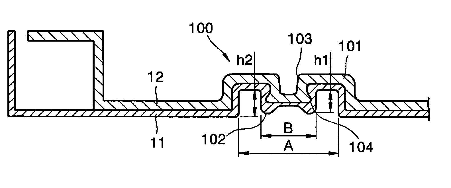
[0029]FIG. 4 is a cross-sectional view of a plate joining structure according to an exemplary embodiment of the present invention.

[0030] Referring to FIG. 4, a plate joining structure 100 according to an exemplary embodiment of the present inv...


PUM

PropertyMeasurementUnit
Shapeaaaaaaaaaa
Widthaaaaaaaaaa
Depthaaaaaaaaaa

Abstract

At least a portion of a first plate and at least a portion of a second plate are arranged to have an overlapping portion, a first deformation unit is formed at the overlapped portion, and a second deformation unit is formed in the first deformation unit. The first deformation unit and the second deformation unit protrude in opposite directions from each other, and the second deformation unit has a smaller cross-sectional width than the first deformation unit. Such a joining structure may be utilized to couple elements together in a display device, such as a plasma display device.

Description

CROSS REFERENCE TO RELATED APPLICATION [0001] This application claims priority to and the benefit of Korean Patent Application No. 10-2004-0085866, filed on Oct. 26, 2004, which is hereby incorporated by reference for all purposes as if fully set forth herein. BACKGROUND OF THE INVENTION [0002] 1. Field of the Invention [0003] The present invention relates to a method for joining plates and a plate joining structure, and more particularly, to a method for joining plates using plastic deformation of plates and a plate joining structure. [0004] 2. Discussion of the Background [0005]FIG. 1 is a perspective view of a display module that may be employed in a plasma display device. [0006] Referring to FIG. 1, the display module includes a display panel 50, a plurality of driving circuit boards 40 having circuits for driving the display panel 50, and a chassis 10 that supports the display panel 50 and the driving circuit boards 40. [0007] The display panel 50 includes a front substrate 51 ...

Claims


Application Information

Patent Timeline
IPC IPC(8): G02F1/1333B21D39/03B21D53/00
CPCH05K5/02Y10T29/53735Y10T29/49936Y10T29/53709H01J9/24H01J11/34
Inventor KIM, SOK-SAN
Owner SAMSUNG SDI CO LTD
Why Eureka
Try Eureka