Heat dissipation structure for display panel and display module equipped with the structure

a technology for display panels and display modules, which is applied in the direction of casings/cabinets/drawers, instruments, casings/cabinets/drawers, etc., to achieve the effect of efficient dissipation of heat generated

Inactive Publication Date: 2006-05-11
SAMSUNG SDI CO LTD
View PDF7 Cites 29 Cited by
  • Summary
  • Abstract
  • Description
  • Claims
  • Application Information

AI Technical Summary

Benefits of technology

[0010] The present invention provides a heat dissipation structure for a display panel which can efficiently dissipate heat generated during the operation of the display panel, and a display module including the heat dissipation structure.
[0011] The present invention also provides a heat dissipation structure for a display panel which can prevent electromagnetic waves generated during the operation of the display panel from affecting a driving circuit.

Problems solved by technology

However, an air layer is formed between the heat dissipating sheet and the chassis base, and thus, only a portion of the heat dissipating sheet contacts the chassis base.

Method used


Image

  • Heat dissipation structure for display panel and display module equipped with the structure
  • Heat dissipation structure for display panel and display module equipped with the structure
  • Heat dissipation structure for display panel and display module equipped with the structure

Examples


first embodiment

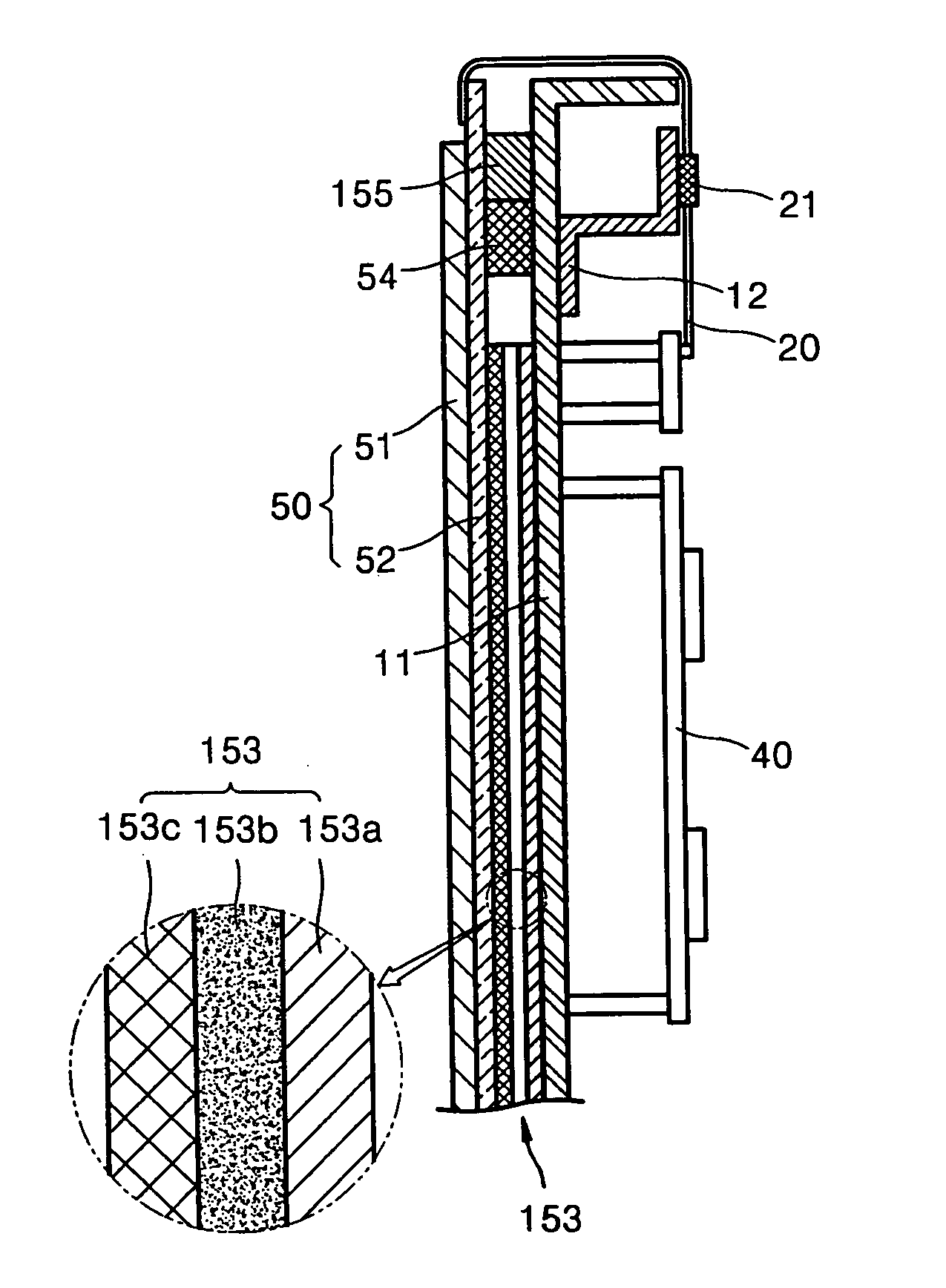
[0038]FIG. 3 is a cross-sectional view of a heat dissipation structure of a display panel according to the present invention.

[0039] Referring to FIG. 3, the heat dissipation structure of a display panel according to the first embodiment includes a display panel 50, a heat dissipating sheet 153, and a chassis base 11.

[0040] The display panel 50 is not limited to a plasma display panel, which is described herein merely as an example, and any display panel which generates heat during its operation and which needs to dissipate the heat for cooling may be used.

[0041] The heat dissipating sheet 153 contacts a rear surface of the display panel 50 and transmits the heat generated during the operation of the display panel 50 to the chassis base 11 for dissipation. The heat dissipating sheet 153 includes two heat dissipating layers 153a and 153c which are made of graphite, which has a high thermal conductivity, and a metal sheet layer 153b interposed between the heat dissipating layers 153a...

second embodiment

[0046]FIG. 4 is a cross-sectional view of a heat dissipation structure of a display panel 50 according to the present invention.

[0047] Referring to FIG. 4, the heat dissipation structure according to the present embodiment includes the display panel 50, a heat dissipating sheet 153, a chassis base 11, and an Electro Magnetic Interference sponge or EMI sponge 155.

[0048] The display panel 50 and the heat dissipating sheet 153 of FIG. 4 are the same as the display panel 50 and the heat dissipating sheet 153 of FIG. 3.

[0049] In the present embodiment, the chassis base 11 is composed of a conductive material.

[0050] The EMI sponge 155 is formed by adhering a conductive fabric, a conductive film or a metal foil to the outside of an elastic sponge, and it is disposed in a region where the heat dissipating sheet 153 is not disposed between the display panel 50 and the chassis base 11. That is, the EMI sponge 155 is disposed on the opposite side of a double-sided adhesive element 54 from t...

third embodiment

[0052]FIG. 5 is a cross-sectional view of a heat dissipation structure of a display panel 50 according to the present invention.

[0053] Referring to FIG. 5, the heat dissipation structure includes the display panel 50, a heat dissipating sheet 153, a chassis base 11, and an EMI sponge 155.

[0054] The display panel 50 and the heat dissipating sheet 153 of FIG. 5 are the same as the display panel 50 and the heat dissipating sheet 153 of FIGS. 3 and 4.

[0055] The chassis base 11 according to the present embodiment is composed of a conductive material.

[0056] The EMI sponge 155 is formed by adhering a conductive fabric, a conductive film or a metal foil to the outside of an elastic sponge as in FIG. 4, but the EMI sponge 155 contacts a metal sheet layer 153b included in the heat dissipating sheet 153 between the display panel 50 and the chassis base 11. That is, the EMI sponge 155 is disposed on the same side of the double-side adhesive element 54 as the heat dissipating sheet 153. The E...


PUM


Abstract

A heat dissipation structure for a display panel efficiently dissipates heat generated during operation of the display panel, and a display module including the heat dissipation structure is also so characterized. The heat dissipation structure is capable of preventing electromagnetic waves generated during the operation of the display panel operation from adversely influencing a driving circuit. The heat dissipation structure comprises: a display panel; a heat dissipating sheet contacting a rear surface of the display panel; and a chassis base disposed on a rear side of the heat dissipating sheet and connected to the display panel via a double-sided adhesive element. The heat dissipating sheet includes two heat dissipating layers and a metal sheet layer interposed between the two heat dissipating layers.

Description

CLAIM OF PRIORITY [0001] This application makes reference to, incorporates the same herein, and claims all benefits accruing under 35 U.S.C. § 119 from an application entitled STRUCTURE FOR HEAT DISSIPATION OF DISPLAY PANEL, AND DISPLAY MODULE EQUIPPED WITH THE SAME, earlier filed in the Korean Intellectual Property Office on Nov. 10, 2004 and there duly assigned Serial No. 10-2004-0091527. BACKGROUND OF THE INVENTION [0002] 1. Technical Field [0003] The present invention relates to a heat dissipation structure for a display panel and a display module equipped with the structure. More particularly, the invention relates to a heat dissipation structure for a display panel which can efficiently discharge heat generated during the operation of the display panel, and which can prevent malfunction of a driving circuit due to electromagnetic waves generated during the operation of the display panel, and a display module equipped with the structure. [0004] 2. Related Art [0005] A display m...

Claims


Application Information

Patent Timeline
Patent Type & Authority Applications(United States)
IPC IPC(8): H05K7/20
CPCH05K7/20963Y10T428/24999H01J11/34H05K5/02H01J5/48G09G2330/045H01J2217/492
Inventor KIM, SOK-SANKIM, KI-JUNGKIM, WON-SUNGKANG, TAE-KYOUNGKIM, MYOUNG-KON
Owner SAMSUNG SDI CO LTD
Why Eureka
Try Eureka