Back light module

a back light and module technology, applied in the field of planar light sources, can solve the problems of poor display weight increase, and achieve the effect of preventing effective cracking and enhancing the quality of liquid crystal displays

Active Publication Date: 2006-05-11
HANNSTAR DISPLAY CORPORATION
View PDF2 Cites 15 Cited by
  • Summary
  • Abstract
  • Description
  • Claims
  • Application Information

AI Technical Summary

Benefits of technology

[0009] It is the object of the invention to provide a back light module to prevent the optical element from cracking during the impact or shock test and enhance the display quality of the liquid crystal display.
[0014] Further, in the optical element of the present invention, the conjunction area between the protrusions and the main body is a fillet with a separate distance g from the side wall of the positioning component. Due to the foregoing design of the present invention, the optical element can be prevented effectively from cracking caused by stress concentration during the impact or shock test and the quality of the liquid crystal display can be enhanced.

Problems solved by technology

However the liquid crystal display itself is incapable of emitting light, so that it needs to use a back light module under the liquid crystal display as the light source for display purpose.
However, with the recently lunched liquid crystal display in bigger size, the weight gets larger, accordingly.
As a result, the crack on the positioning component 150 causes the poor display quality of the liquid crystal display and people need to handle with such problem by improving design.

Method used


Image

  • Back light module
  • Back light module
  • Back light module

Examples


first embodiment

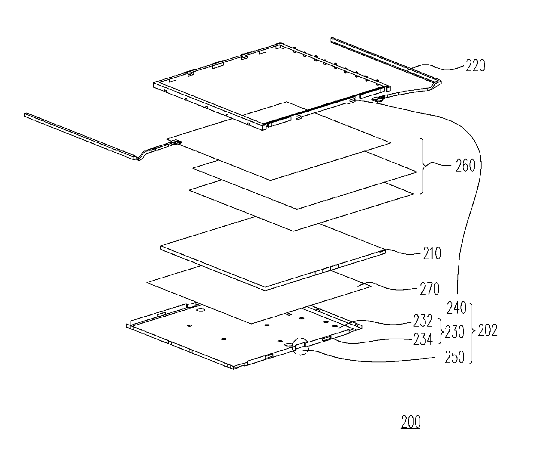
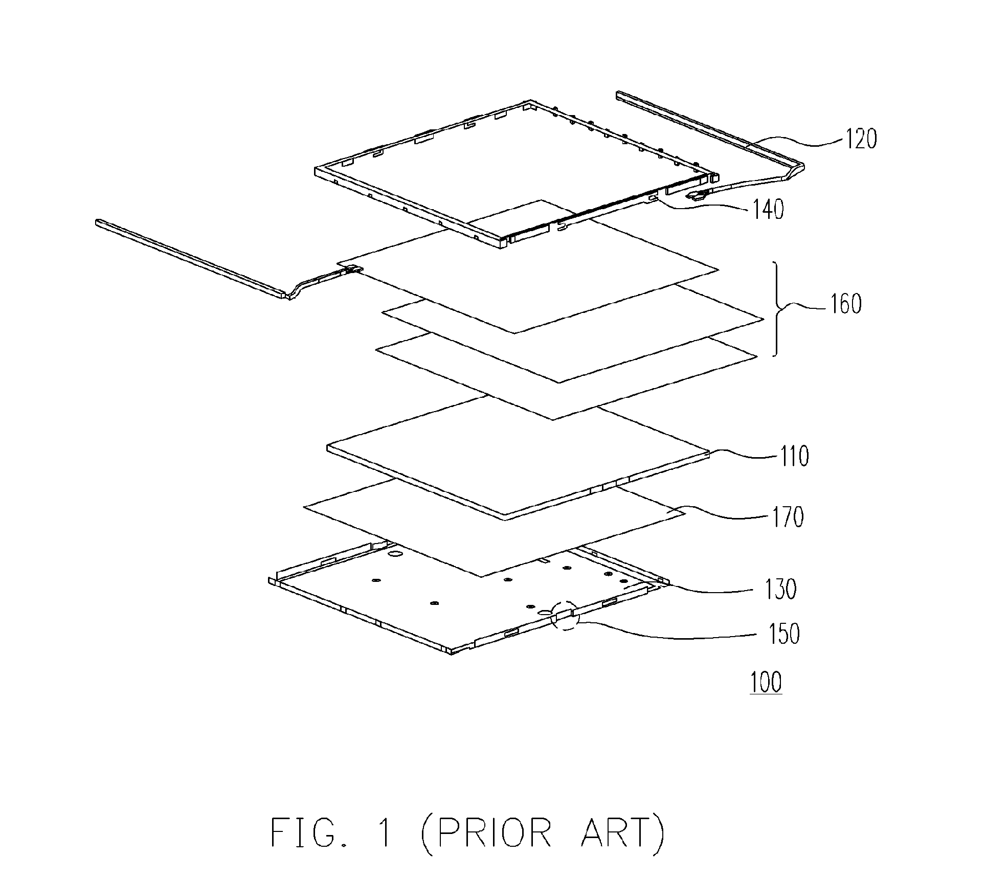
[0027]FIG. 3 is a drawing, schematically illustrating an exploded view of a back light module, according to the present invention. The back light module 200 includes an optical element 210, a light source 220, an outer supporting means 202, a plurality of optical films 260 and a reflection sheet 270. The outer supporting means 202 is used to fix the optical element 210 and the light source 220. In addition, the outer supporting means 202 can include a back plate 230, a front frame 240, one or more positioning components 250. The light source 220 is disposed approach, including beside or underneath, to the optical element 210. The optical element 210 can be a light guide plate or a diffusion sheet. The back plate 230 supports the optical element 210 and the light source 220. The light source 220 can be a cold cathode fluorescent lamp or light emitting diode. In addition, the front frame 240 is used for fixing the optical element 210 and the light source 220 onto the back plate 230. T...

second embodiment

[0030]FIGS. 5A-5B are perspective and planar views, schematically illustrating the assembly of the positioning component, according to the present invention. In FIGS. 5A and 5B, the protrusion 314 takes trapezoid form and the included angle between the inner wall 356 and the side wall 352 is an obtuse angle. In this embodiment, the outer wall 334 is in conjunction with the side wall 352 of the positioning component 350. Preferably, the out wall 334 is formed by bending an edge of the back plate and the positioning component 350 is formed by cutting a region of the back plate, and thereby bending another region of the outer wall 334. Wherein, the side walls 352 and the transition walls 354 are formed automatically during forming the positioning component 350. The protrusions 314 are covered by the outer wall 334 and the side wall 352.

third embodiment

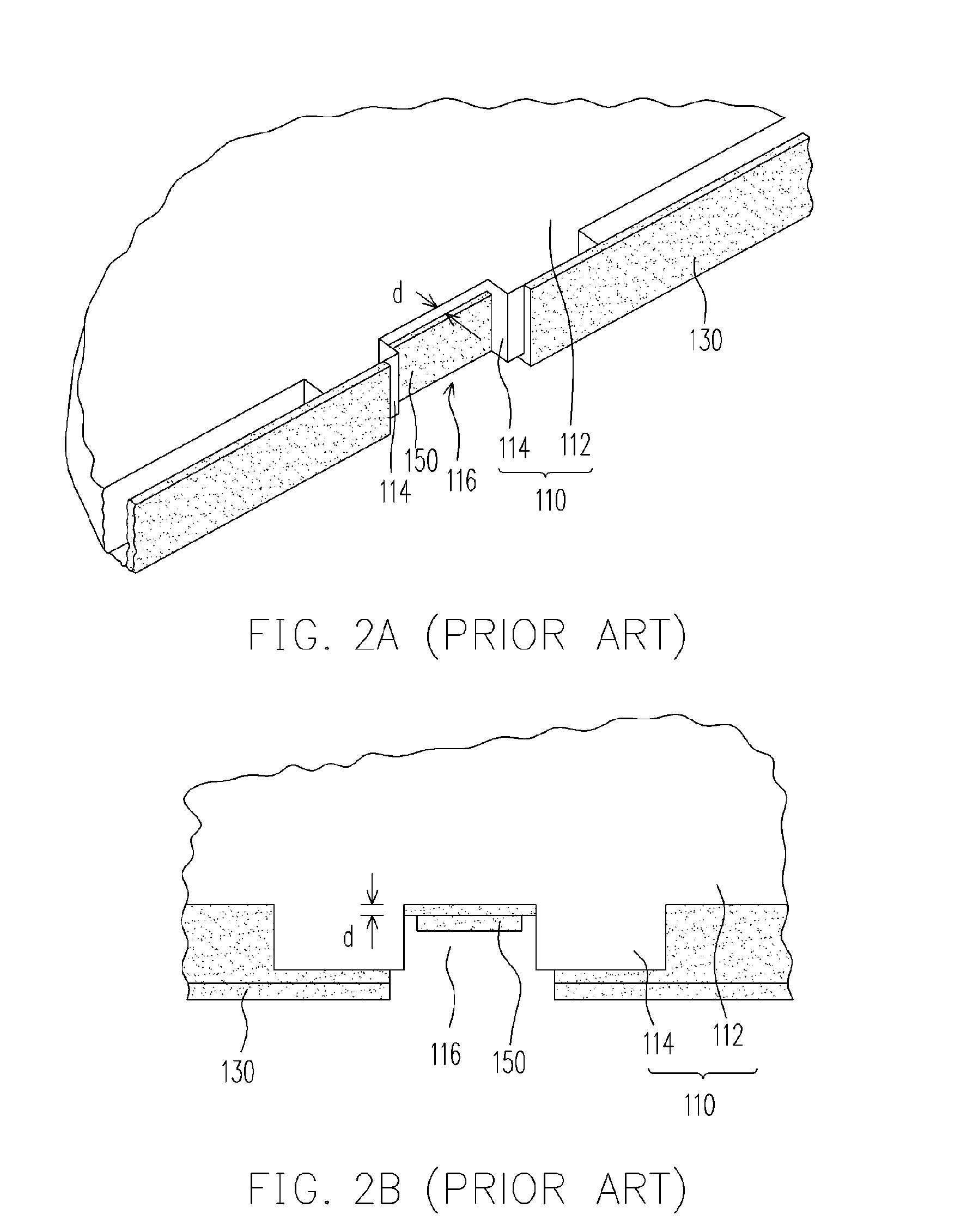
[0031]FIGS. 6A-6B are perspective and planar views, schematically illustrating the assembly of the positioning component, according to the present invention. The protrusions of this embodiment protrude from the side wall 452 and are covered by the outer wall 434. Preferably, the out wall 434 is formed by bending an edge of the back plate 430. FIG. 6C is a cross-sectional view, along the line B-B in FIG. 6A. In FIGS. 6A-6C of this embodiment, the positioning groove 416 and the positioning component 450 are covered by the outer wall 434. In addition, it can be seen from FIG. 6C that the positioning component 450 is formed by cutting a region of the back plate 430, and thereby bending the region. The side walls 452 are formed by bending the edges of the positioning component 450 and the transition walls 454 are formed automatically during forming the side walls 452. In FIG. 6C, it can be noted that there are a third separate distance d3 between the inner wall 456 and the outer wall 434...


PUM


Abstract

The present invention provides a back light module, having an optical element, a light source and an outer supporting means. The optical element includes main body and protrusions which protrude from an edge of the main body. Contiguous protrusions with the main body form a positioning groove. The conjunction region between protrusion and main body is a fillet. The outer supporting means fixes the optical elements and the light source, which has at least one positioning component disposed on the edge of the back plate. The positioning component includes one inner wall near to edge of the main body, a side wall near to the protrusion and a transition wall connecting the side wall and the inner wall. A separate distance g between the fillet and the side wall so that the optical element can be prevented from cracking during the impact or shock test of the back light module.

Description

CROSS-REFERENCE TO RELATED APPLICATION [0001] This application claims the priority benefit of Taiwan application serial no. 93133757, filed on Nov. 5, 2004. BACKGROUND OF THE INVENTION [0002] 1. Field of Invention [0003] The present invention relates to a planar light source, and particularly to a back light module. [0004] 2. Description of Related Art [0005] Today, the digital appliances, such as a mobile phone, a digital camera, a digital video camera, a notebook, a personal computer (PC) and a desktop, have been developed tremendously with more convenience, multi-function and attractive outlook. To use such so-called IT (information technology) products, the screen is indispensable for man-machine interface with more convenient maneuver. Recently the liquid crystal display (LCD) has been the major type of screen for most of the mobile phone, the digital camera, the digital video camera, the notebook, the personal computer and the desktop. However the liquid crystal display itself...

Claims


Application Information

Patent Timeline
Patent Type & Authority Applications(United States)
IPC IPC(8): F21V15/01F21V8/00F21V7/04
CPCG02B6/0086
Inventor KAO, HUNG-CHENLAI, HSIN-CHIEH
Owner HANNSTAR DISPLAY CORPORATION
Why Eureka
Try Eureka