

Blow-forming machine
- Summary
- Abstract
- Description
- Claims
- Application Information
AI Technical Summary
Benefits of technology
Problems solved by technology
Method used
Image

Examples
Embodiment Construction
[0152] Embodiments of a blow molding apparatus according to the present invention will be described with reference to the drawings.
(Overall Structure)
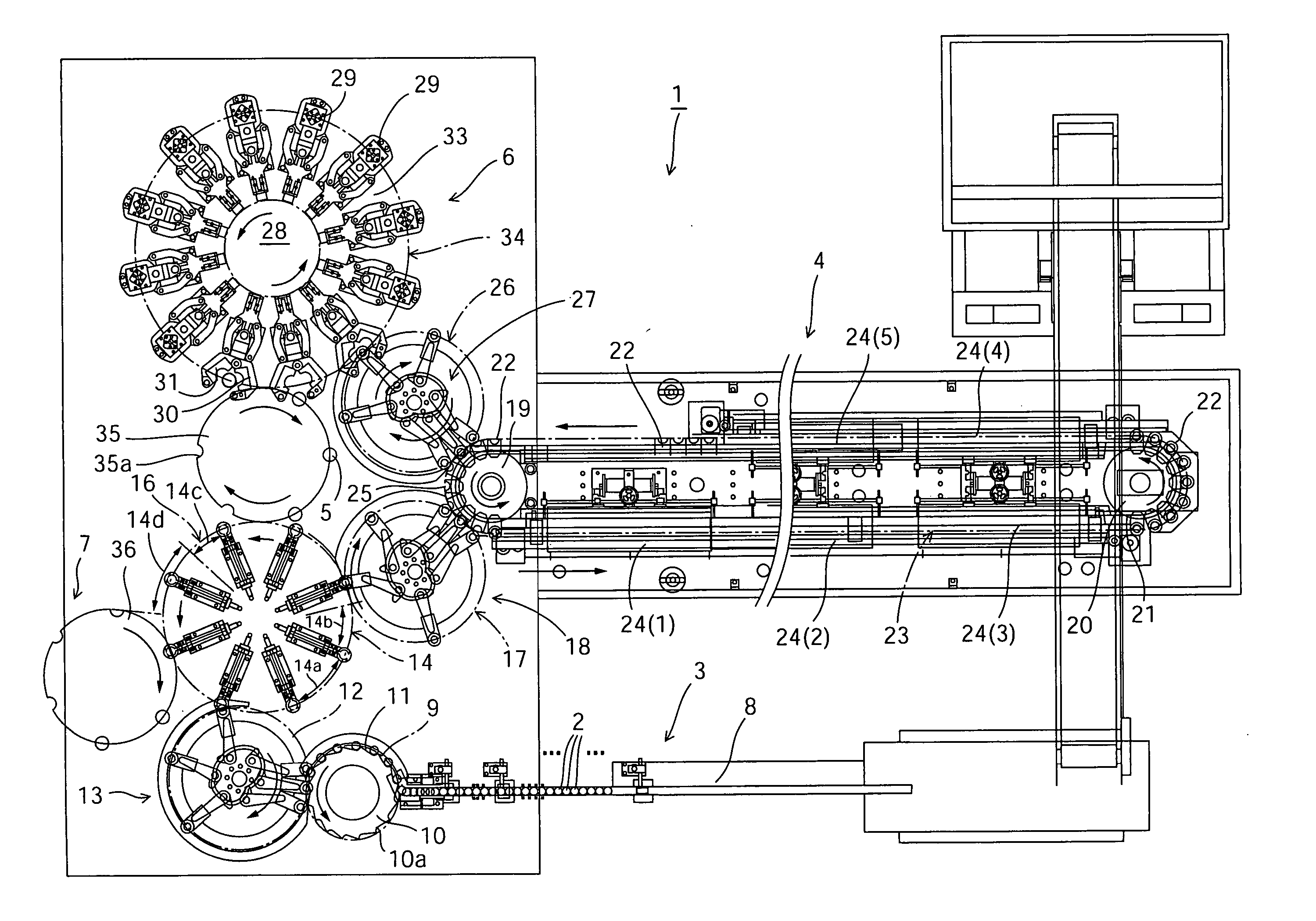
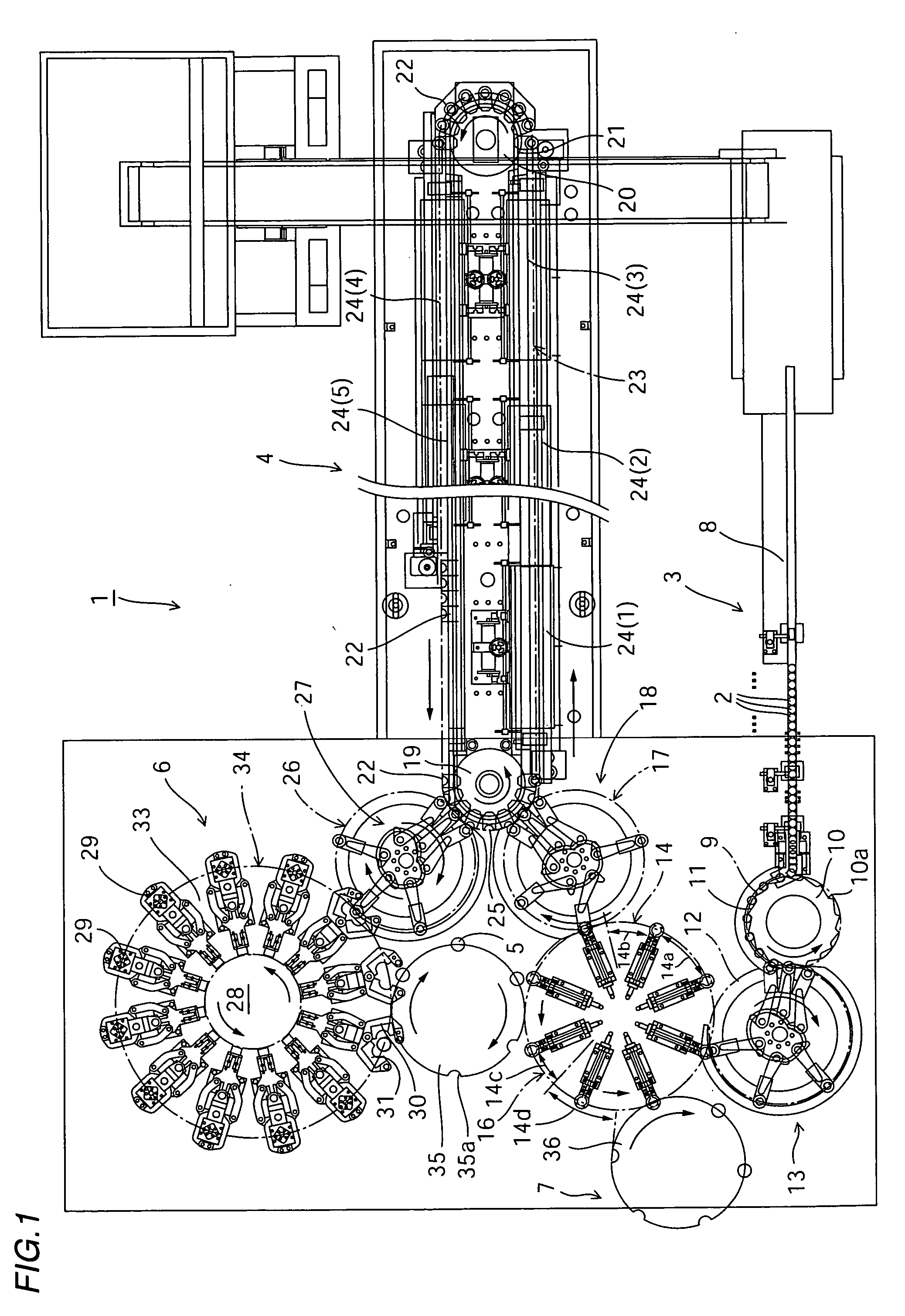
[0153]FIG. 1 is a plan view schematically showing an overall construction of a biaxial stretch blow molding apparatus according to an embodiment of the present invention. In the illustrated example, a biaxial stretch blow molding apparatus 1 is a manufacturing apparatus for PET bottles used for drinks, for example, and has a preform supplying station 3 that supplies preforms 2, a heating station 4 that heats the preforms 2 to a temperature state suitable for blow-molding while transporting the preforms 2, a rotary-type blow station 6 that molds PET bottles 5 (blow-molded products) by blowing the heated preforms 2, and a collection station 7 that collects the PET bottles 5. The preform supplying station 3 includes a guide rail 8 that is inclined downward towards a supplying end, with flanges 2b of opening parts 2a of each preform 2 h...
PUM
| Property | Measurement | Unit |
|---|---|---|
| Angle | aaaaa | aaaaa |
Abstract
Description
Claims
Application Information