Biological optical measurement system
a biological optical measurement and optical measurement technology, applied in the field of optical measurement technology, can solve the problems of difficult to reduce the noise signal of mayer wave using bandpass filter or bandcut filter, and difficult to reduce the noise signal of mayer wave using a simple frequency filter, so as to achieve the effect of reducing the amount of biological noise signal contained in the biological optical measurement signal
- Summary
- Abstract
- Description
- Claims
- Application Information
AI Technical Summary
Benefits of technology
Problems solved by technology
Method used
Image
Examples
embodiment 1
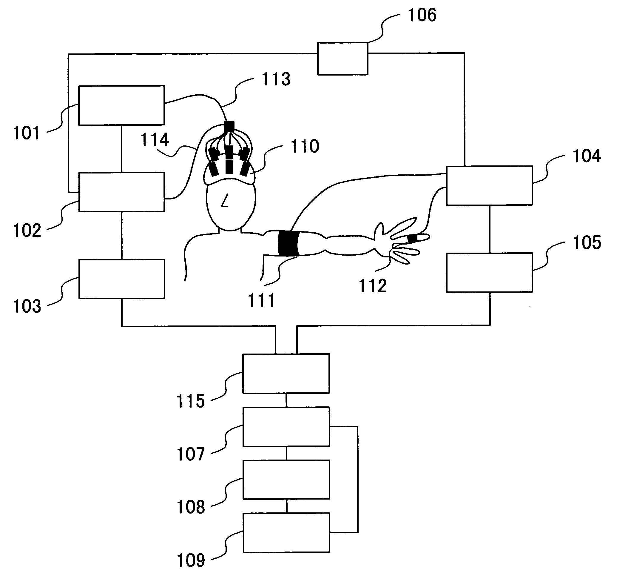
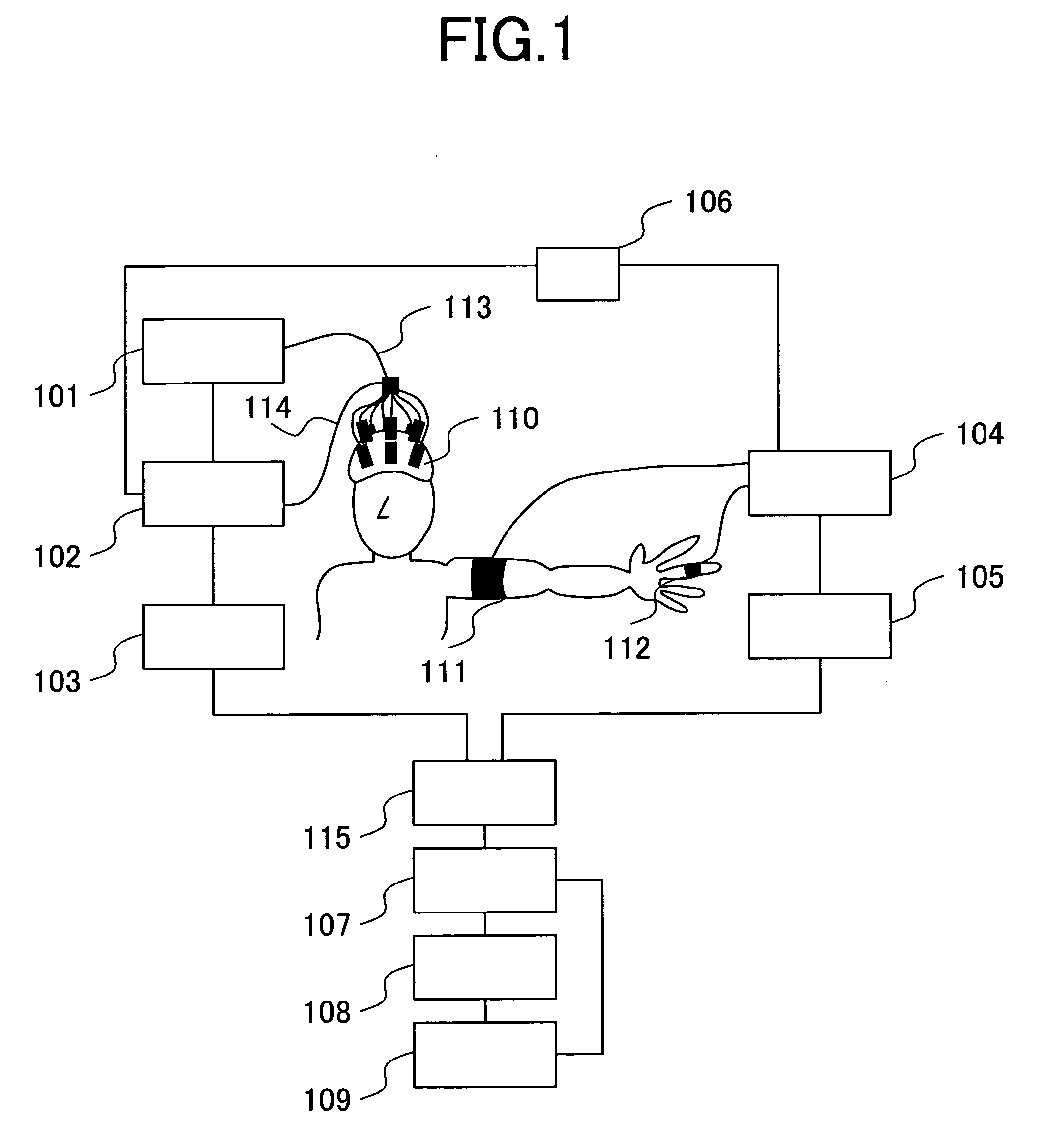
[0033]FIG. 1 shows a diagram of a system according to a first embodiment of the invention.
[0034] In the first step of a procedure, the operator attaches a biological optical measuring probe 110 to a part or the entirety of the head of a subject. The tissue is then irradiated with light produced by a light irradiating unit 101 via optical fibers 113 connected to the biological optical measuring probe 110. The light that has passed through the tissue is then detected by an optical detection unit 102 via an optical fiber 114 connected to the biological optical measuring probe 110. The resultant signal is recorded in a memory unit 103.
[0035] The aforementioned signal recorded in the memory unit 103 is hereafter referred to as “an optical signal.” A blood-pressure measuring cuff 111 for the arm and a blood-pressure measuring cuff 112 for the finger are attached to the arm and a finger, respectively, of the subject. The cuffs, either one of which may be dispensed with, are controlled by...
embodiment 2
[0044]FIG. 5 shows a second embodiment of the invention, in which, instead of the blood pressure measuring cuff 111 for the arm and the blood pressure measuring cuff 112 for the finger in the first embodiment, probes 511 and 512 for the measurement of pulsation using light are employed. The device for measuring pulsation using light is known as a pulse oximeter, the measurement principle of which is the same as that of the present embodiment. The probes for pulsation measurement using light consist of one (511) that is disposed near the head, where optical measurement takes place, such as at the ear or the forehead, and / or the other (512) that is attached to a portion of the subject that is spaced apart from the probe 511 by a certain distance, such as the arm. Signals obtained by the pulsation measurement unit 504 are processed by units including the memory unit 505 and the relationship computing unit 507, as in the first embodiment.
embodiment 3
[0045]FIG. 6 shows a third embodiment of the invention, which includes a measurement unit that is identical to the one in Embodiment 5. A blood-pressure computing unit 613 determines the blood pressure from two signals obtained by a pulsation measurement unit 604 based on the pulsation transfer time (Patent Document 4). Alternatively, the pulsation component may be extracted from an optical signal obtained by an optical detection unit 602 and then used in the blood pressure computation unit 613.
PUM
 Abstract
Description
Claims
Application Information
 - R&D
- Intellectual Property
- Life Sciences
- Materials
- Tech Scout
- Unparalleled Data Quality
- Higher Quality Content
- 60% Fewer Hallucinations
Browse by: Latest US Patents, China's latest patents, Technical Efficacy Thesaurus, Application Domain, Technology Topic, Popular Technical Reports.
© 2025 PatSnap. All rights reserved.Legal|Privacy policy|Modern Slavery Act Transparency Statement|Sitemap|About US| Contact US: help@patsnap.com


