Variable expansion force stent

a stent and variable technology, applied in the field of stents, can solve the problems of irritating non-stenose tissue, stent ends may flare outward, protruding into non-stenose tissue, and likely less than optimal for the wider region, so as to achieve greater expansion, less expansion, and greater force

Inactive Publication Date: 2006-05-11
BOSTON SCI SCIMED INC
View PDF2 Cites 2 Cited by
  • Summary
  • Abstract
  • Description
  • Claims
  • Application Information

AI Technical Summary

Benefits of technology

[0014] Stents made in accordance with the present invention can provide an outward radial force more closely matching the local force requirements. In particular, the stents provide greater force only where required in a stenosis center, without providing too much force in the region of healthy tissue. The stents provide an expanded geometry more closely tailored to the requirements of a narrowing vessel region, providing greater expansion in wider regions and less expansion in narrower regions.

Problems solved by technology

The stent ends may thus flare outward, protruding into, and possibly irritating non-stenosed tissue.
If this force is properly matched for the narrower vessel opening, it is likely less than optimal for the wider region.

Method used


Image

  • Variable expansion force stent
  • Variable expansion force stent
  • Variable expansion force stent

Examples


Embodiment Construction

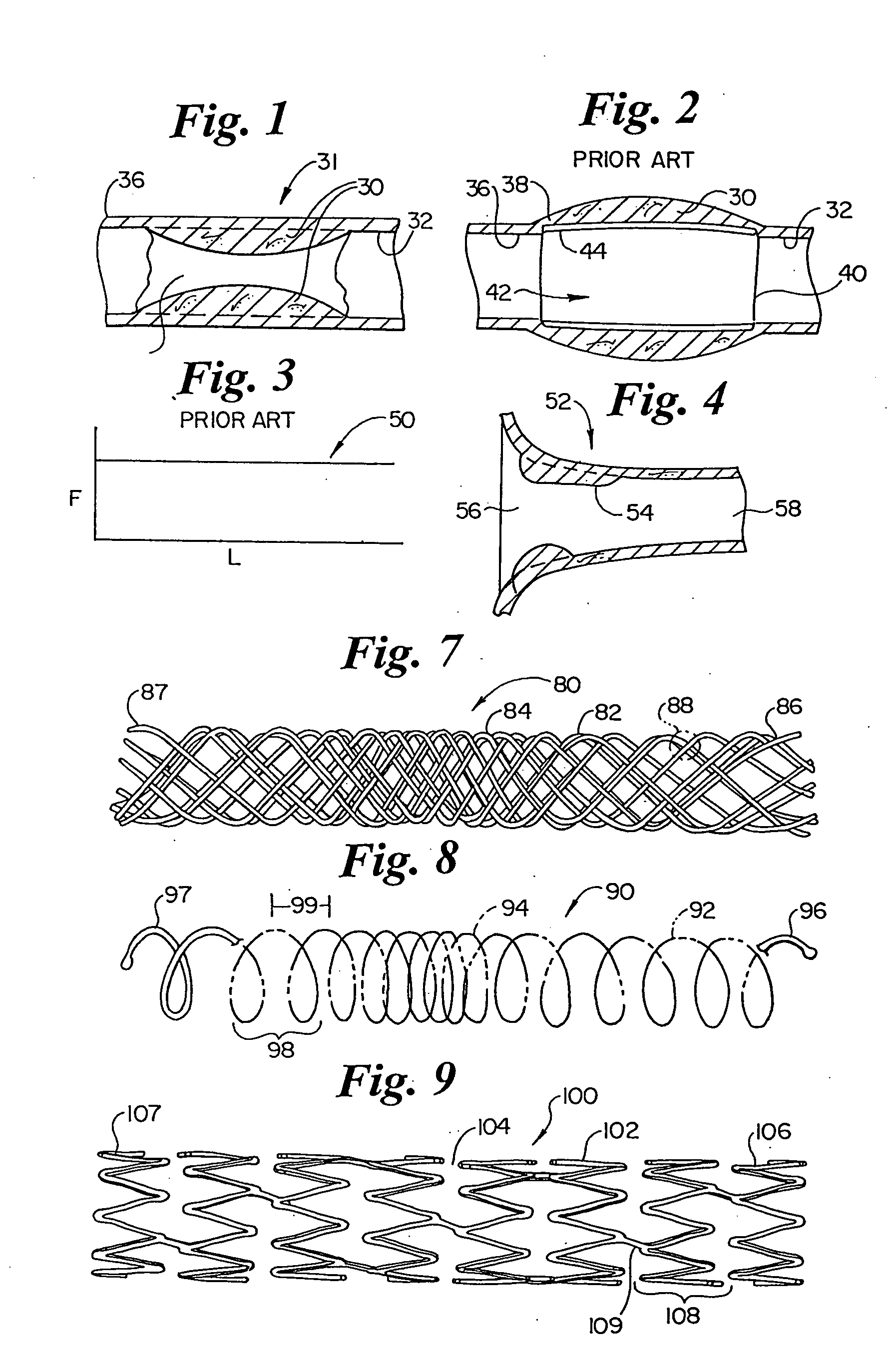
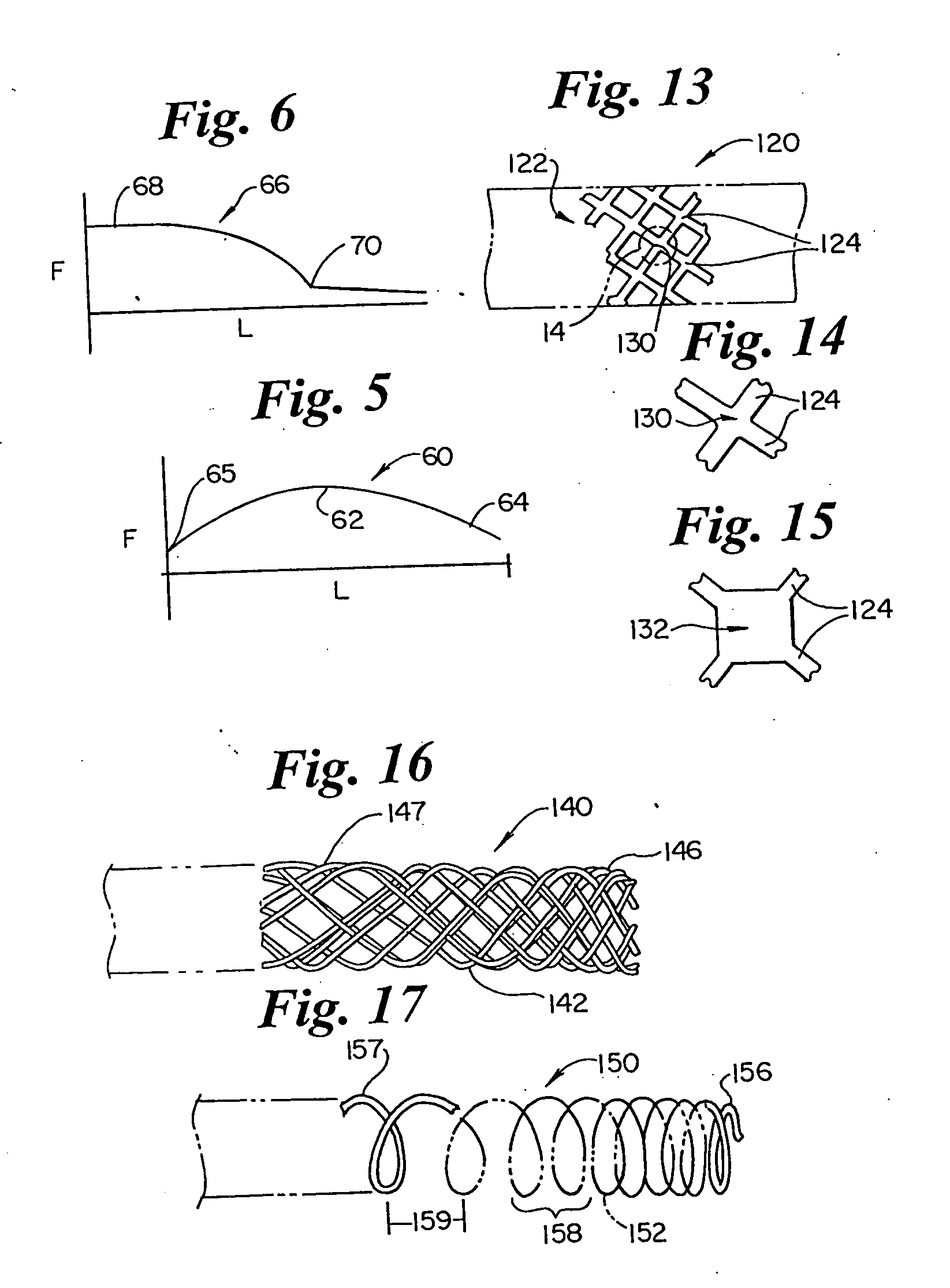
[0032]FIG. 1 illustrates a stenosis 30, forming narrowed region 34, in a vessel 31 within vessel wall 32. Adjacent to stenosis 30 is a healthy vessel region 36. FIG. 2 illustrates a conventional stent 40 in place across stenosis 30, out of the blood flow channel as indicated at 44. Stent 40 includes a stent end 44, shown angling into healthy vessel area 36 at 38. Stent 40 as shown, has sufficient force to keep vessel 30 open against the rebound force of stenosis 30, and has more force than required at stent end 42, resulting in stent 40 angling into the healthy vessel wall at 38. FIG. 3 illustrates an idealized plot 50 of outward radial force, F, against stent length, L, for a conventional stent such as that illustrated in FIG. 2. As shown, the force is substantially constant over the length.

[0033]FIG. 4 illustrates a narrowing vessel 52 having a wide region 56, a narrowed region 58, and a stenosis 54. The narrowing vessel of FIG. 4 illustrates the geometry as found in an ostium su...


PUM


Abstract

A stent having varying outward radial force along its length. In use, the stent can provide greater force in vessel regions requiring greater force and less force in regions requiring less. In particular, more force is provided in the narrowed, center of a stenosis, while not applying too much force to the adjoining healthy tissue area. Greater stent expansion is provided in wider vessel geometries and less stent expansion in narrower regions. Varying force is achieved varying the number of elements, the density of elements, and the thickness of the elements.

Description

FIELD OF THE INVENTION [0001] The invention relates generally to medical devices. More specifically, the invention relates to stents for holding vessels such as arteries open to flow. BACKGROUND OF THE INVENTION [0002] Stents are insertable medical devices used to maintain openings for fluid flow in areas that might otherwise close, hindering flow. Stents are used to prevent restenosis after Percutaneous Transluminal Catheter Angioplasty (PTCA), presenting outward radial force against a potentially rebounding vessel wall after balloon widening. Stents are also used to hold open inflamed vessel walls that would otherwise be swollen shut, precluding flow. Stents can also be used to hold open surgically made holes for drainage. [0003] Stents are often tubular devices for insertion into tubular vessel regions. Balloon expandable stents require mounting over a balloon, positioning, and inflation of the balloon to expand the stent radially outward. Self-expanding stents expand into place ...

Claims


Application Information

Patent Timeline
Patent Type & Authority Applications(United States)
IPC IPC(8): A61F2/06A61F2/00A61F2/82A61F2/88A61F2/90
CPCA61F2/88A61F2/90A61F2/91A61F2/915A61F2002/30014A61F2002/30093A61F2002/30199A61F2002/30322A61F2002/30324A61F2002/30327A61F2002/821A61F2002/91533A61F2002/91558A61F2210/0019A61F2230/0063A61F2250/0018A61F2250/0026A61F2250/0036A61F2250/0039A61F2002/30092
Inventor ST. GERMAIN, JON P.
Owner BOSTON SCI SCIMED INC
Why Eureka
Try Eureka