
User position utilizaion system

a user position and user technology, applied in the field of user position utilizaion system, can solve the problems of reducing the number of subscribers, difficult to distribute temporally free advertisements, and requiring considerable expense in the location of aps

Inactive Publication Date: 2006-05-11
FUJITSU LTD
View PDF4 Cites 12 Cited by
  • Summary
  • Abstract
  • Description
  • Claims
  • Application Information

AI Technical Summary

Benefits of technology

The present invention provides a system for utilizing information related to a user's position to distribute advertisements to customers who meet certain conditions. The system includes a memory unit that stores information about the user's position, access point, and user. The system can extract this information and use it to send advertisements to the user's email address. The system can also include an authentication server that transmits electronic certificates to the user's terminal, which can be used for authentication purposes. The invention allows for the efficient distribution of advertisements to customers and ensures reliable authentication.

Problems solved by technology

The location of AP requires considerable expense, and for that reason, most of the access point services are charged services such as a monthly rate system.
However, when the service starts for free but thereafter moves from free to fee based, there is a tendency to reduce the number of subscribers after moving to fee based, and therefore the service provider wants to provide the service with no fee.
However, because the conventional art presumes the advertisement with respect to the subscriber who presently exists on the access point, it is difficult to distribute the advertisement that is temporally free.
This is because the advertisement delivery to a customer who is in the store presently can be performed by delivering the advertisement to a terminal accessing a network, but there arises a problem in that the above method cannot be performed in the case where the advertisement is to be delivered to the customer who has come to the store in the past but is not in the store presently.

Method used


Image

  • User position utilizaion system
  • User position utilizaion system
  • User position utilizaion system

Examples


applied example 1

OF CUSTOMER POSITIONAL INFORMATION TABLE

[0160] Subsequently, a description will be given of an applied example 1 of the information (when, where, who) stored in the customer positional information table as described above with reference to the drawings.

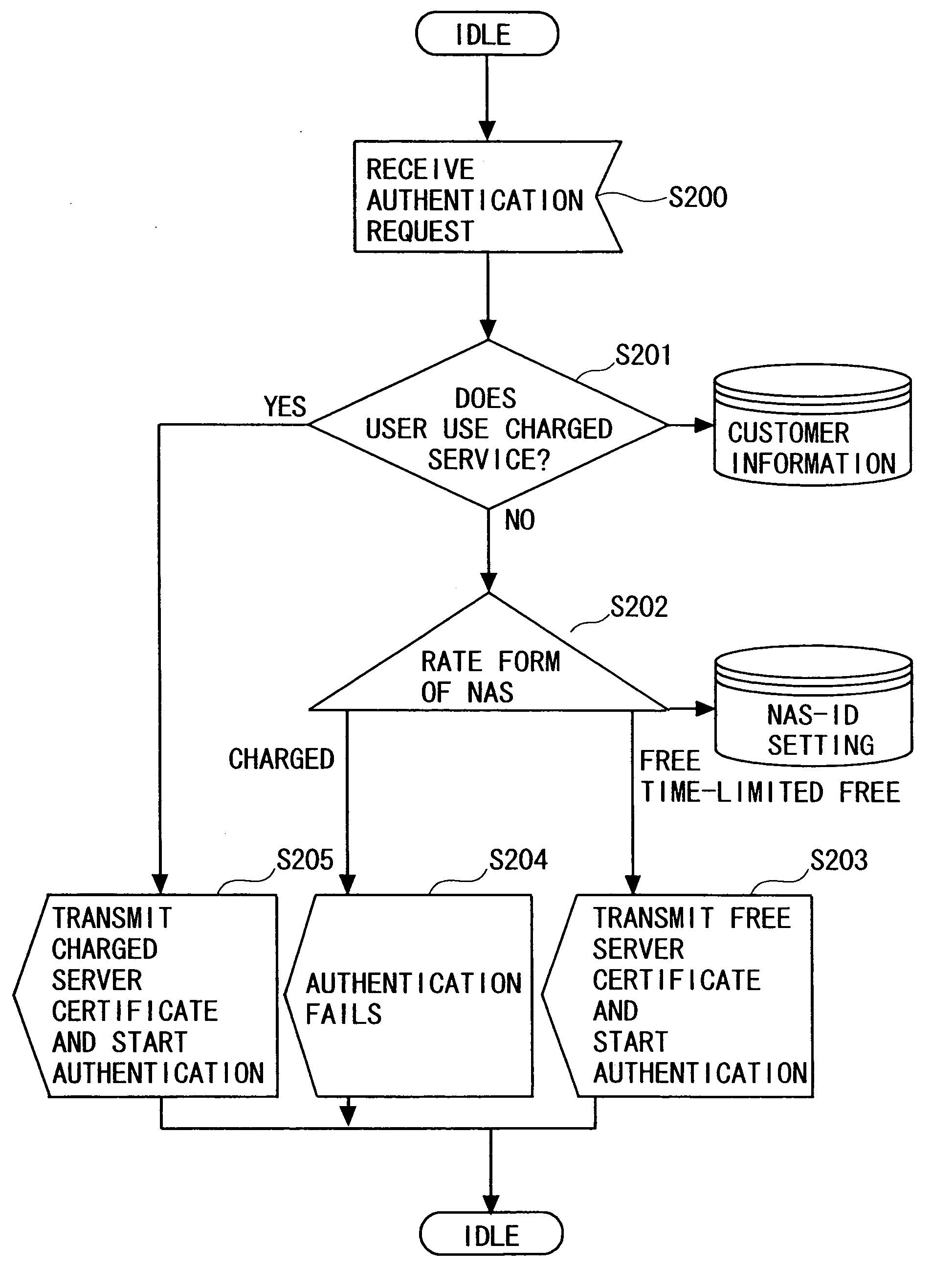
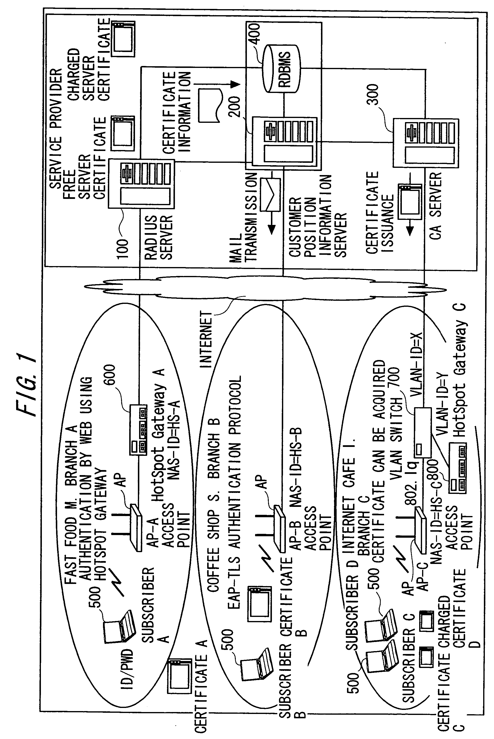
[0161] As shown in FIG. 12, it is assumed that the customer positional information server 200 receives the authentication information from the RADIUS server 100 (S400). The customer positional information server 200 obtains the access point name from the NAS-ID in the authentication information (S401). For that reason, the customer positional information server 200 collates the NAS-ID set table and the NAS-ID in the authentication information. A correspondence of the NAS-ID with the access point (location) is stored in the NAS-ID set table. Accordingly, the collation makes it possible to obtain the access point name (location) corresponding to the NAS-ID in the authentication information.

[0162] Subsequently, the customer positional ...

applied example 2

OF CUSTOMER POSITIONAL INFORMATION TABLE

[0165] Subsequently, a description will be given of an applied example 2 of the information (when, where, who) stored in the customer positional information table as described above with reference to the drawings.

[0166] As shown in FIG. 13, it is assumed that the customer positional information server 200 receives a clock from a timer within the system or the like (S500). The clock occurs, for example, every set time. The customer positional information server 200 retrieves the service B select access point (S501). For the retrieval, the customer positional information server 200 refers to the access point set table. A correspondence of the access point (location) with the advertisement service (service types such as a service A or B) is stored in the access point set table. Accordingly, the reference makes it possible to retrieve the access point that selects the service B.

[0167] The customer positional information server 200 judges whether...

modified example

[0174] Subsequently, a modified example will be described. When the authentication is conducted by the X.509 electronic certificate, there arises such a problem on the security that the information (name, etc.) within the certificate can be referred to from a radio monitor. In order to solve the above problem, the name within the electronic certificate is set to a virtual name in this modified example. Specifically, the CA server 300 generates the virtual names at random, and generates a virtual name conversion table that associates the subscriber names with the virtual names respectively. FIG. 14 shows an example of the virtual name conversion table. When preparing the authentication information, the CA server 300 converts the virtual name into the subscriber name by using the table.

[0175] The above process makes it possible to solve the problem on the security since the information within the certificate is the senseless virtual name even if the information within the certificate...


PUM


Abstract

A system utilizing information on a user position via an IP network. The system includes storage unit for storing information for identifying a date and time when a user terminal has become communicable in a communication area provided by a predetermined radio LAN access point, information identifying the access point, and information identifying the user, and utilization unit for utilizing the information stored in the storage unit.

Description

CROSS-REFERENCE TO RELATED APPLICATION [0001] This is a continuation of Application PCT / JP2003 / 011554, filed on Sep. 10, 2003, now pending, the contents of which are herein wholly incorporated by reference.BACKGROUND OF THE INVENTION [0002] 1. Field of the Invention [0003] The present invention relates to a technique of utilizing information (when, where, who) related to a position of a user terminal (its user) that enters a communication area provided by a given radio LAN access point. [0004] 2. Description of the Related Art [0005] Up to now, in the case where a service provider provides an access point of a public radio LAN, it is necessary to locate a radio LAN access point (hereinafter referred to also as “AP”) at respective locations. [0006] The location of AP requires considerable expense, and for that reason, most of the access point services are charged services such as a monthly rate system. [0007] However, when the service starts for free but thereafter moves from free to...

Claims


Application Information

Patent Timeline
Patent Type & Authority Applications(United States)
IPC IPC(8): H04L9/00H04K1/00G06Q10/00G06Q30/02G06Q30/06G06Q50/00G06Q50/30G06Q50/32G07C9/00G09C1/00H04L9/32H04L12/28H04L29/06H04L29/08H04W4/06H04W4/12H04W8/20H04W12/00H04W48/08H04W60/00H04W84/12
CPCG07C9/00134H04L9/0897H04L9/321H04L9/3226H04L9/3263H04L9/3271H04L63/0823H04L63/10H04W4/02H04W8/22H04W84/12H04W88/08H04L67/24H04L67/20H04L67/18G07C9/32H04L67/53H04L67/54H04L67/52
Inventor KOBAYASHI, KAZUTOSHI
Owner FUJITSU LTD
Learn More