Bed ventilator

a technology for ventilating beds and beds, applied in the field of bed accessories, can solve the problems of affecting the efficiency of sleep, requiring a relatively large amount of energy to function appropriately, and wasting energy, and achieve the effects of reducing the risk of altering the sleep structure, low noise and vibration level, and convenient installation

Inactive Publication Date: 2006-05-18
LUSSIER JEAN
View PDF4 Cites 31 Cited by
  • Summary
  • Abstract
  • Description
  • Claims
  • Application Information

AI Technical Summary

Benefits of technology

[0019] Also, the proposed bed ventilator is adapted to provide a comfortable flow of air to the sleeper so as to reduce the risks of altering the sleep architecture by micro-awakenings, or the like.
[0020] Also, the proposed bed ventilator is adapted to regulate the humidity of the air about the body of the bed occupants.
[0021] Still furthermore, the proposed bed ventilator is designed so as to be efficient and to operate with a relatively low noise and vibration level.
[0022] Furthermore, the proposed bed ventilator is designed so as to be readily installable at various strategic locations on numerous types of beds without requiring special tooli

Problems solved by technology

Indeed, it is well known that if the temperature adjacent the sleeper becomes uncomfortable, not only may the sleeper wake up, but the sleeping pattern may be altered resulting in a less efficient sleep.
Although somewhat efficient at maintaining a comfortable ambient temperature, such units require a relatively large amount of energy to function appropriately.
Furthermore, they typically require that the entire room be cooled, sometimes leading to a considerable waste of energy.
Hence, both the purchase and maintenance of such air conditioning units may prove to be unduly costly.
Indeed, it is well known that the body of the average sleeper releases a substantial amount of heat through skin loss and moisture due to perspiration to the surrounding air.
While somewhat efficient, the method consisting in using numerous sheets and blankets nevertheless suffers from some drawbacks.
Indeed, the use of numerous layers or even of a single relatively heavy layer for the maintenance of a desired temperature creates an undue weight of overlying insul

Method used


Image

  • Bed ventilator
  • Bed ventilator
  • Bed ventilator

Examples


Embodiment Construction

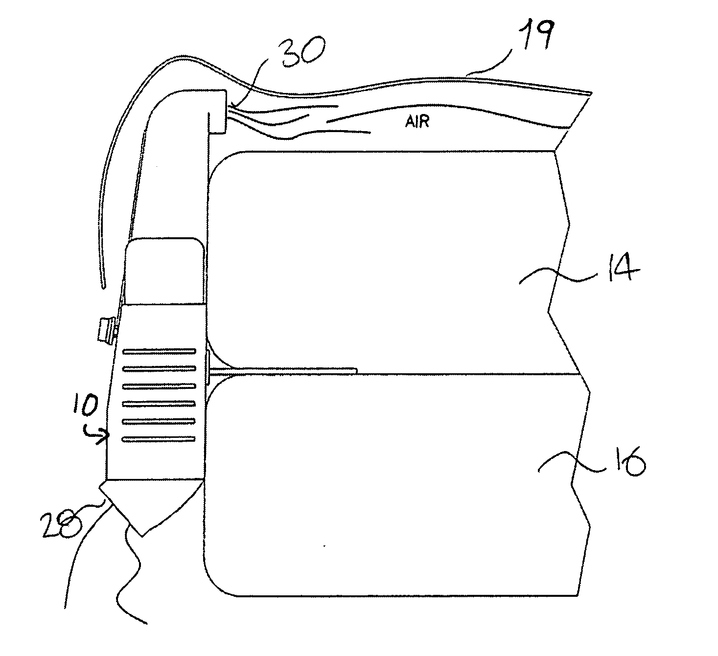
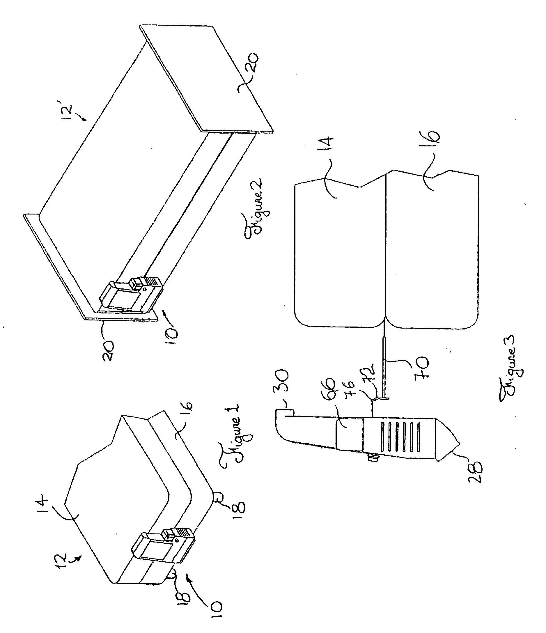
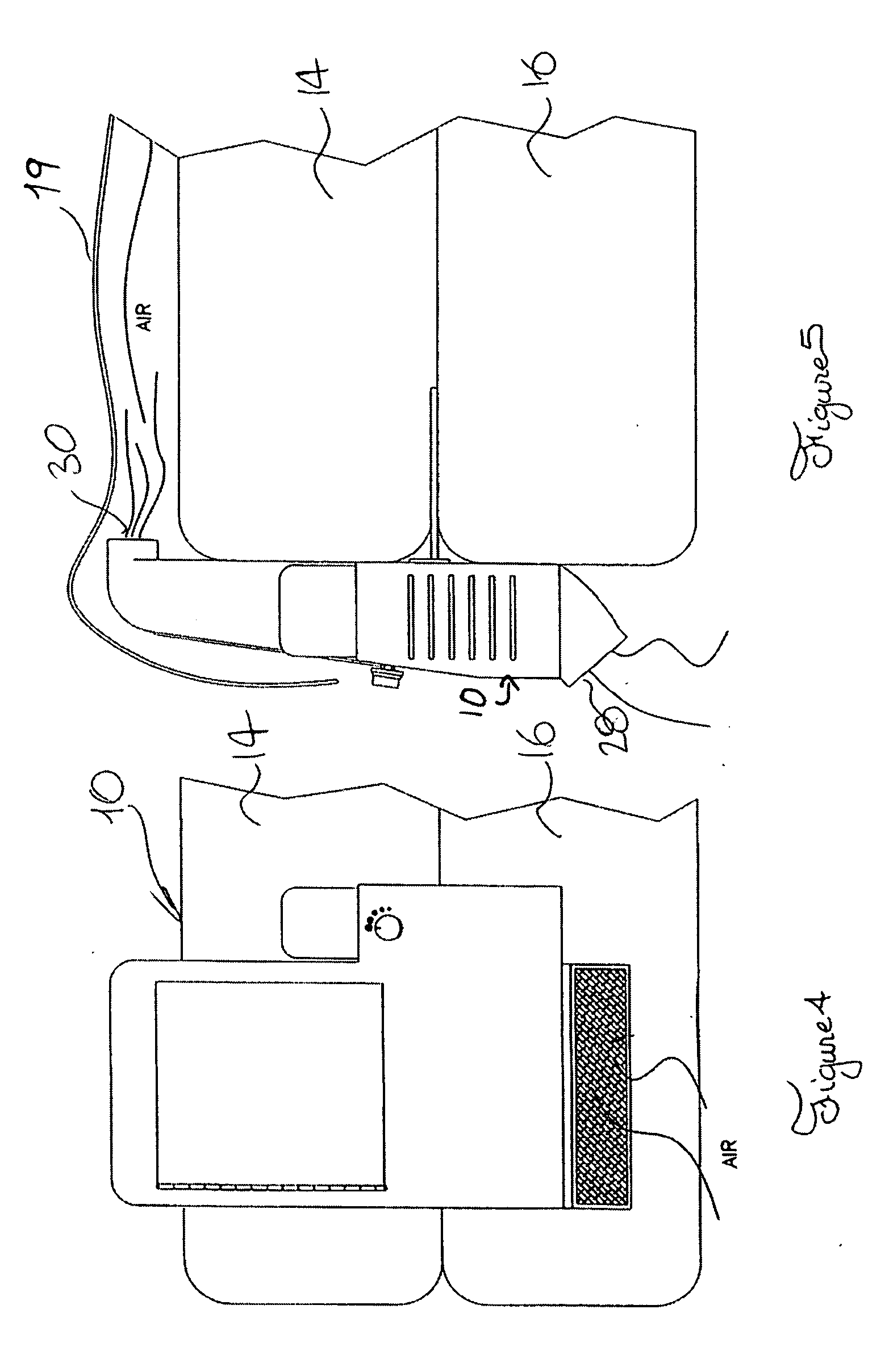
[0047] Referring to FIG. 1, there is shown a bed ventilator in accordance with an embodiment of the present invention, the bed ventilator being generally indicated by the reference numeral 10. The bed ventilator 10 is shown mounted adjacent to the base of a conventional bed 12. The conventional bed 12 is shown including a substantially parallelepiped-shaped mattress 14 resting on a substantially similarly shaped box spring 16. The bed 12 is also shown including bed legs 18 extending from the box spring 16.

[0048] Although the bed 12 includes a mattress 14 resting on a box spring 16, it is within the scope of the invention to use the bed ventilator 10 with a bed including any other type of mattress support supporting the mattress 14. For example, the mattress 14 could be supported by a wood board, among other possibilities

[0049] It should be understood that the bed ventilator 10 could be used in other contexts such as with other types of beds, or even other types of furniture, or ev...


PUM


Abstract

A bed ventilator for drawing surrounding air thereinto, treating the surrounded air drawn thereinto with a selected air treatment component so as to produce treated air and blowing the treated air under a bed covering of a bed, the bed including a mattress and a mattress support supporting the mattress. The bed ventilator includes: a casing including an inlet, an outlet and a passageway extending therebetween for fluidly coupling the inlet and the outlet, the casing being configured and sized so that the outlet is positionable under the bed covering; an air circulator located between the inlet and the outlet for drawing the surrounding air through the inlet and blowing the treated air outwardly from the outlet; and a treatment component support mechanically coupled to the casing for removably supporting the air treatment component within said casing.

Description

[0001] This Application claims priority from UK Patent Application Serial Number 0425089.0 filed on Nov. 13, 2004. FIELD OF THE INVENTION [0002] The present invention relates to the general field of bed accessories, and is particularly concerned with a bed ventilator. BACKGROUND OF THE INVENTION [0003] The therapeutic value resulting from bed rest is largely dependant on the quality of sleep which, in turn, is largely dependant upon the degree of comfort afforded to the sleeper by the environment. One important factor directly affecting the quality of bed rest is the maintenance of temperature in the immediate environment of the sleeper within an optimal temperature range. [0004] Indeed, it is well known that if the temperature adjacent the sleeper becomes uncomfortable, not only may the sleeper wake up, but the sleeping pattern may be altered resulting in a less efficient sleep. Various methods have been used in the prior art to provide a relatively comfortable sleeping environment...

Claims


Application Information

Patent Timeline
IPC IPC(8): A47C31/00A47C27/00A47C21/04
CPCA47C21/044A47C21/048
Inventor LUSSIER, JEAN
Owner LUSSIER JEAN
Why Eureka
Try Eureka