Engine misfire detection

Inactive Publication Date: 2006-05-18
LOTUS ENG
View PDF20 Cites 31 Cited by
  • Summary
  • Abstract
  • Description
  • Claims
  • Application Information

AI Technical Summary

Benefits of technology

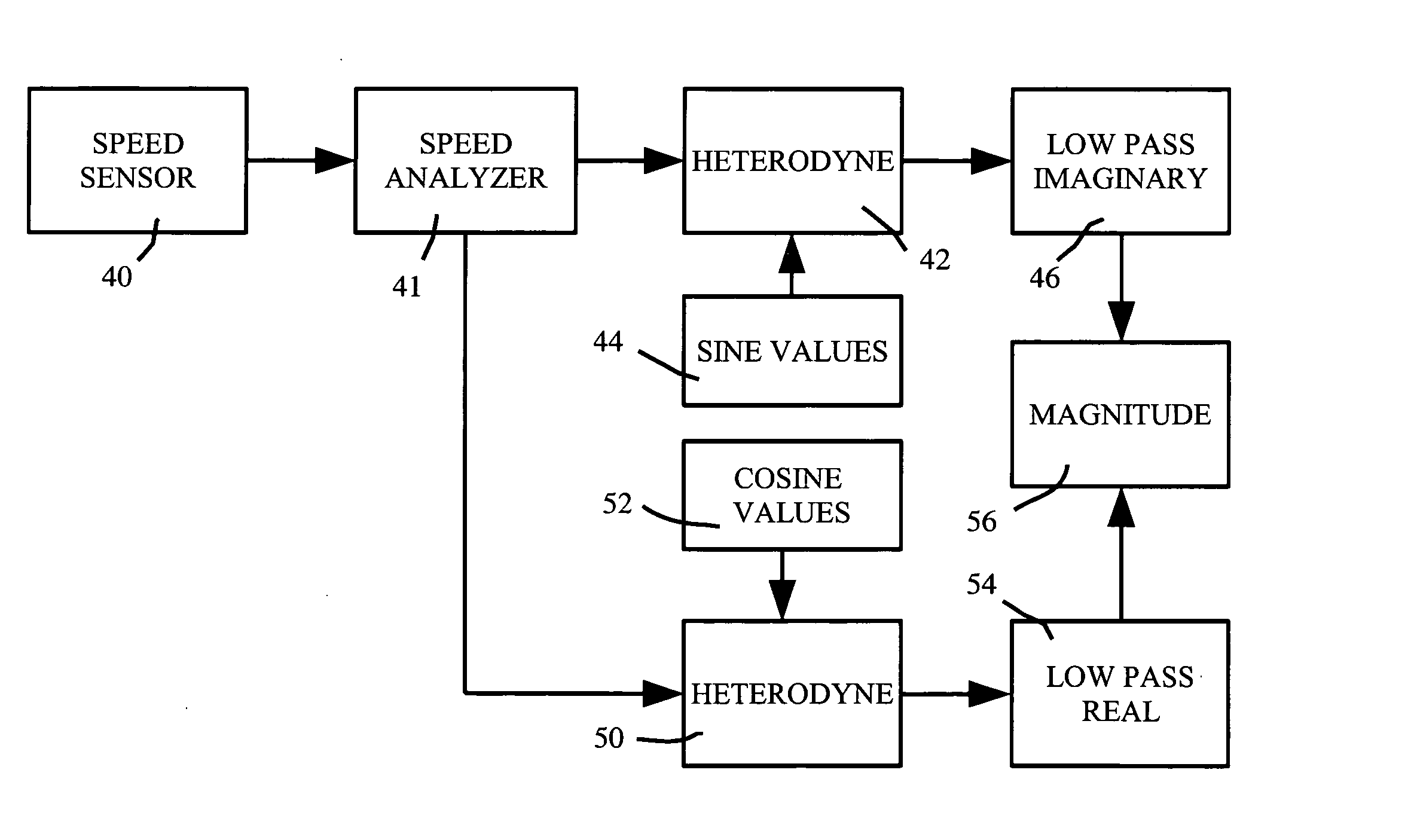
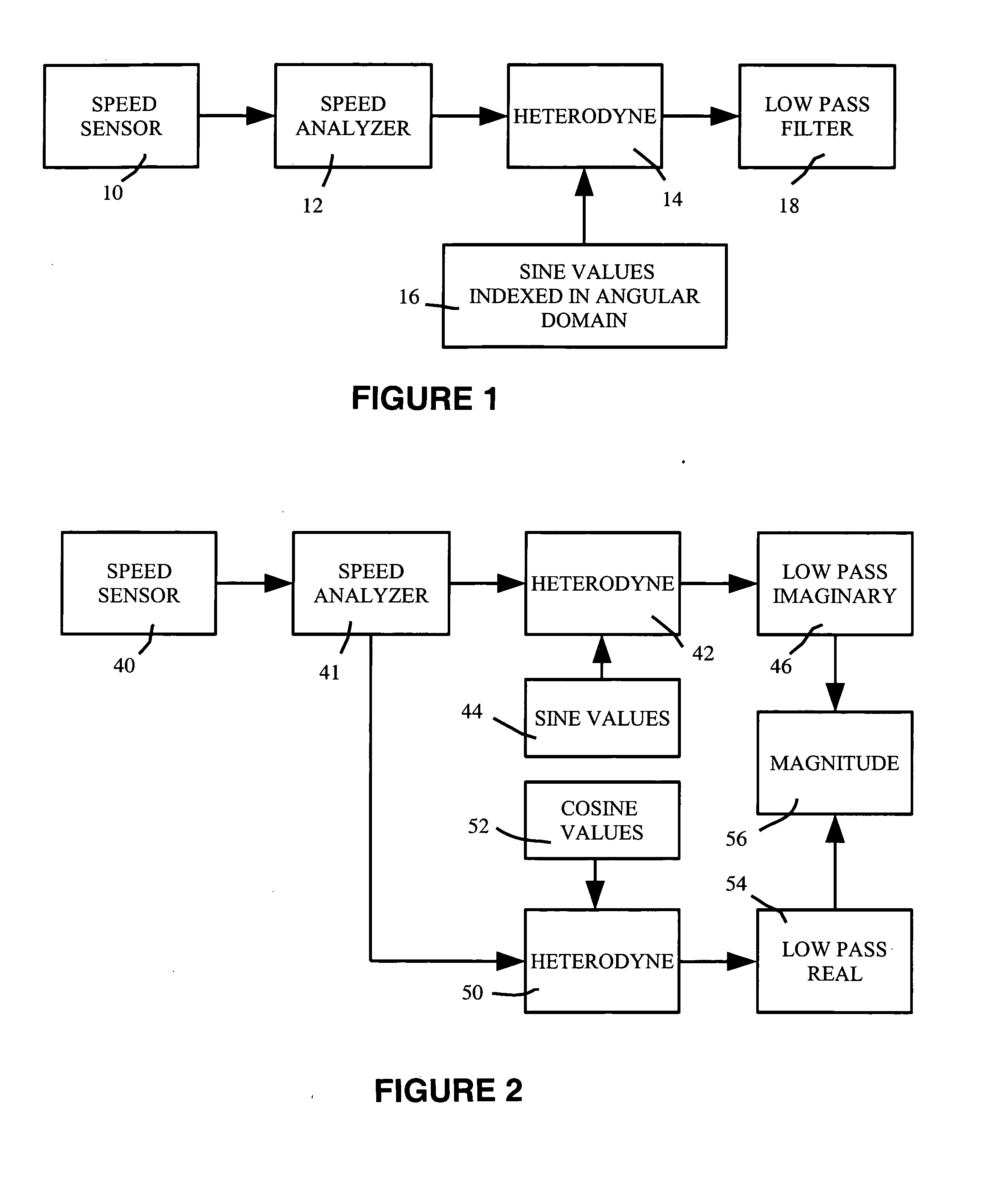
[0005] A method of detecting an engine malfunction such as a misfire includes determining engine speed values at each of a plurality of measurement angular positions, heterodyning the engine speed values with sine and cosine functions

Problems solved by technology

Engine misfire leads to degradation in engine performance.
Furthermore, it can lead to unburned fuel leaving the engine in exhaust gases.
Hence,

Method used


Image

  • Engine misfire detection
  • Engine misfire detection
  • Engine misfire detection

Examples


Embodiment Construction

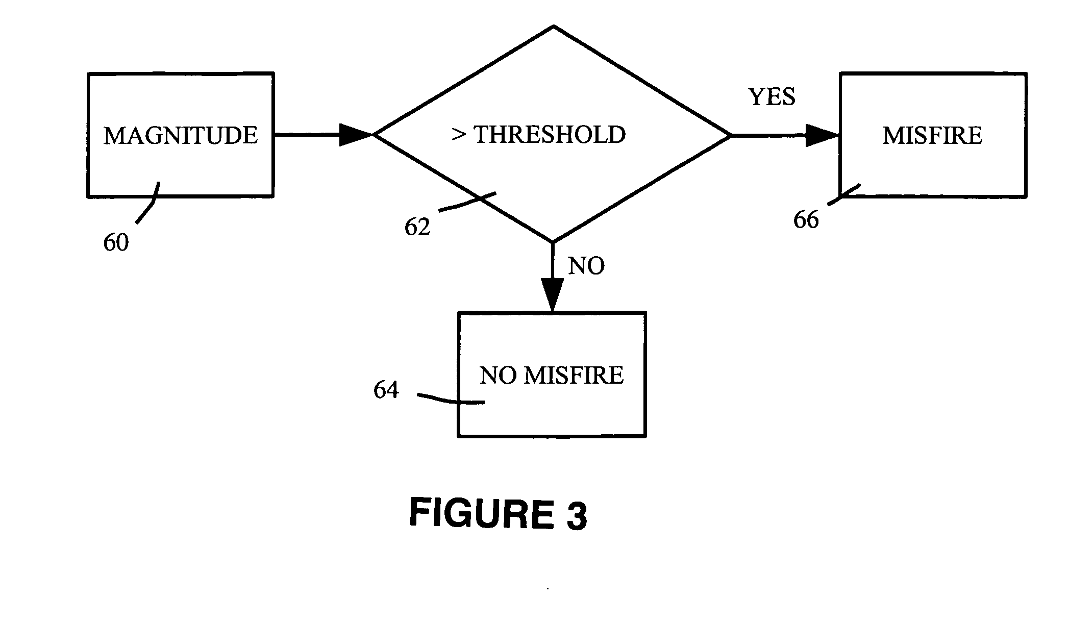
[0014] In a conventional four-stroke multi-cylinder engine, any given cylinder fires once every two revolutions of the engine. A single cylinder misfire in any multi-cylinder engine causes a strong half-order engine speed variation (also called a torsional velocity signature), which can be detected as part of an improved engine management system. Hence, the half order (and sometimes the first order) torsional vibration magnitude is a strong indicator of engine misfire.

[0015] First order analysis can be useful for engines with certain type of ignition systems where cylinders are paired on a common ignition coil, as a pair of cylinders misfiring 360 degrees apart generates a strong first order signature.

[0016] In this application, terms such as “first-order,”“half-order,” etc. relate to torsional vibrations at multiples of engine speed. A first-order signal repeats once per engine revolution, and a half-order signal repeats once per two engine revolutions. The term “engine speed” re...


PUM


Abstract

A method of detecting an engine malfunction such as a misfire includes determining engine speed values at each of a plurality of measurement angular positions, heterodyning the engine speed values with sine and cosine functions indexed in the angular domain, passing the heterodyned results through a low pass filter, and computing the resulting magnitude from the resulting two vectors. An apparatus for detecting an engine malfunction, such as a misfire, includes an engine speed analyzer, a multiplier, and a low pass filter.

Description

REFERENCE TO RELATED APPLICATION [0001] This application claims priority of U.S. Provisional Patent Application Ser. No. 60 / 628,334, filed Nov. 15, 2004, the entire content of which is incorporated herein by reference.FIELD OF THE INVENTION [0002] The invention relates to engine diagnostic apparatus and methods, in particular, to engine misfire detection. BACKGROUND OF THE INVENTION [0003] Engine misfire leads to degradation in engine performance. Furthermore, it can lead to unburned fuel leaving the engine in exhaust gases. A catalytic converter is often provided to reduce the amount of pollutants in exhaust gases, and part of the function of the catalytic converter is to induce combustion of unburned fuels on a surface of the catalytic converter. Hence, if appreciable amounts of unburned fuel are present in the exhaust gases, the catalytic converter will overheat, and can be rapidly destroyed. [0004] Hence, it would be desirable to provide improved engine misfire detection methods...

Claims


Application Information

Patent Timeline
IPC IPC(8): G01M15/00G21C17/00
CPCG01M15/11
Inventor CHRISTENSEN, JAMES R.
Owner LOTUS ENG
Why Eureka
Try Eureka