
Managing structure for umbilical member of industrial robot

a technology of umbilical members and industrial robots, applied in the direction of mechanical control devices, instruments, process and machine control, etc., can solve the problems of interference between the umbilical member and a peripheral equipment, the frequency of maintenance of wires or tubes may be increased, and the difficulty in stabilizing the motion so as to facilitate the change of the arrangement of the umbilical member. , the effect of flexible chang

Inactive Publication Date: 2006-05-18
FANUC LTD
View PDF5 Cites 31 Cited by
  • Summary
  • Abstract
  • Description
  • Claims
  • Application Information

AI Technical Summary

Benefits of technology

[0009] An object of the present invention is to resolve the above problems. In other words, one object of the invention is to provide a managing structure for an umbilical member, by which the motion of the umbilical member is not so changed even when the orientation of the work tool is greatly changed by rotation of the wrist axis of the robot, whereby the stress applied to a wire or a tube constituting the umbilical member may become smaller. Also, another object of the invention is to provide a managing structure for an umbilical member capable of easily changing the arrangement of the umbilical member at an installation site of the robot, so as to flexibly allow the modification of a system including the robot.

Problems solved by technology

However, in such a configuration in which the umbilical member is arranged over the forearm of the robot, when the orientation of the work tool is greatly changed by rotation of a wrist axis of the robot, it is difficult to make the motion of the umbilical member stable.
As a result, the frequency of the maintenance of the wire or the tube may be increased by the deterioration of the life, or damage to, the wire or the tube.
Further, the unstable motion of the umbilical member may cause interference between the umbilical member and a peripheral equipment.
The above problem may be solved by this configuration to some extent, however, a robot must be individually prepared to correspond to an operation of a system using the robot, whereby the production cost of the robot becomes larger.

Method used


Image

  • Managing structure for umbilical member of industrial robot
  • Managing structure for umbilical member of industrial robot
  • Managing structure for umbilical member of industrial robot

Examples


Embodiment Construction

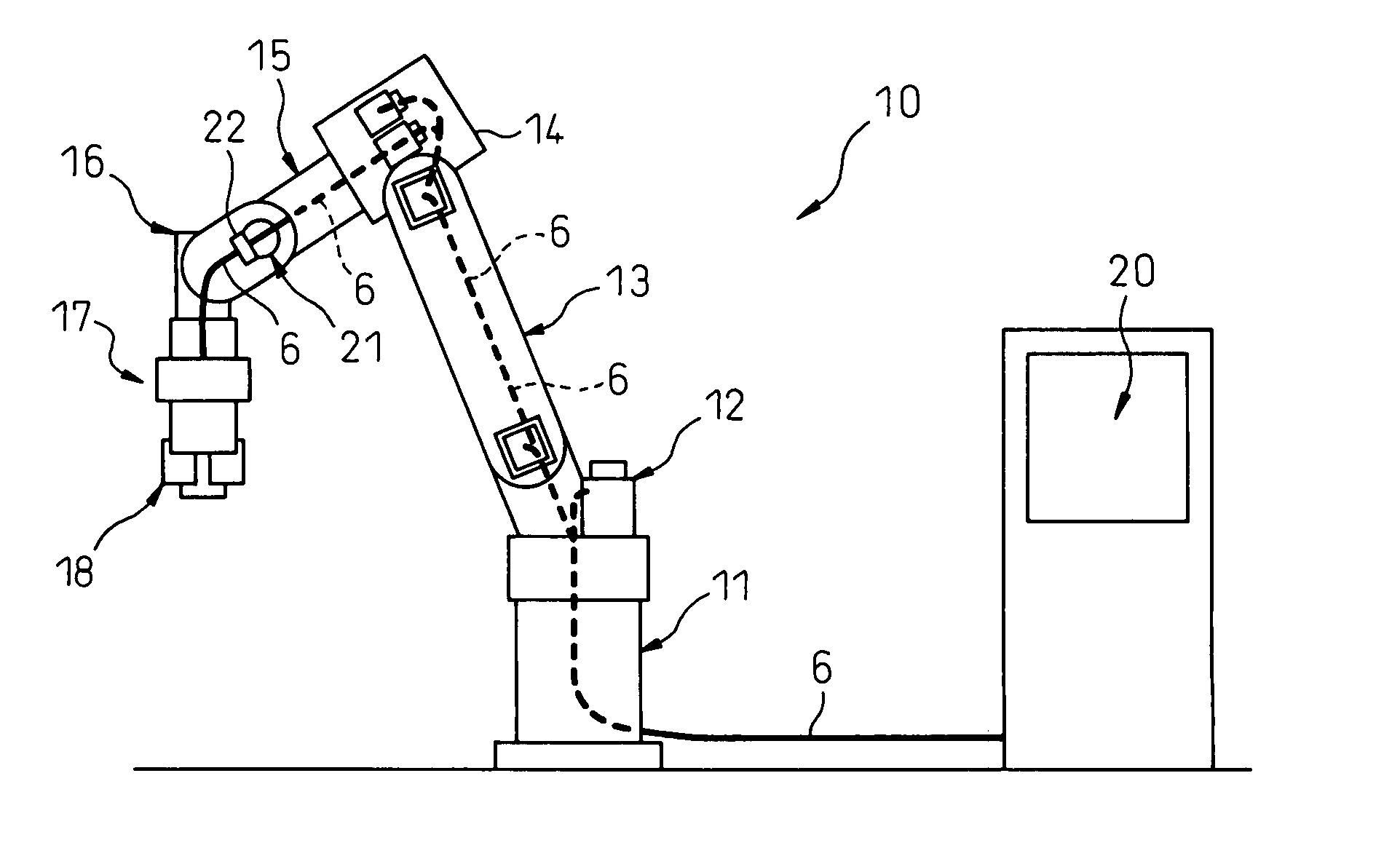
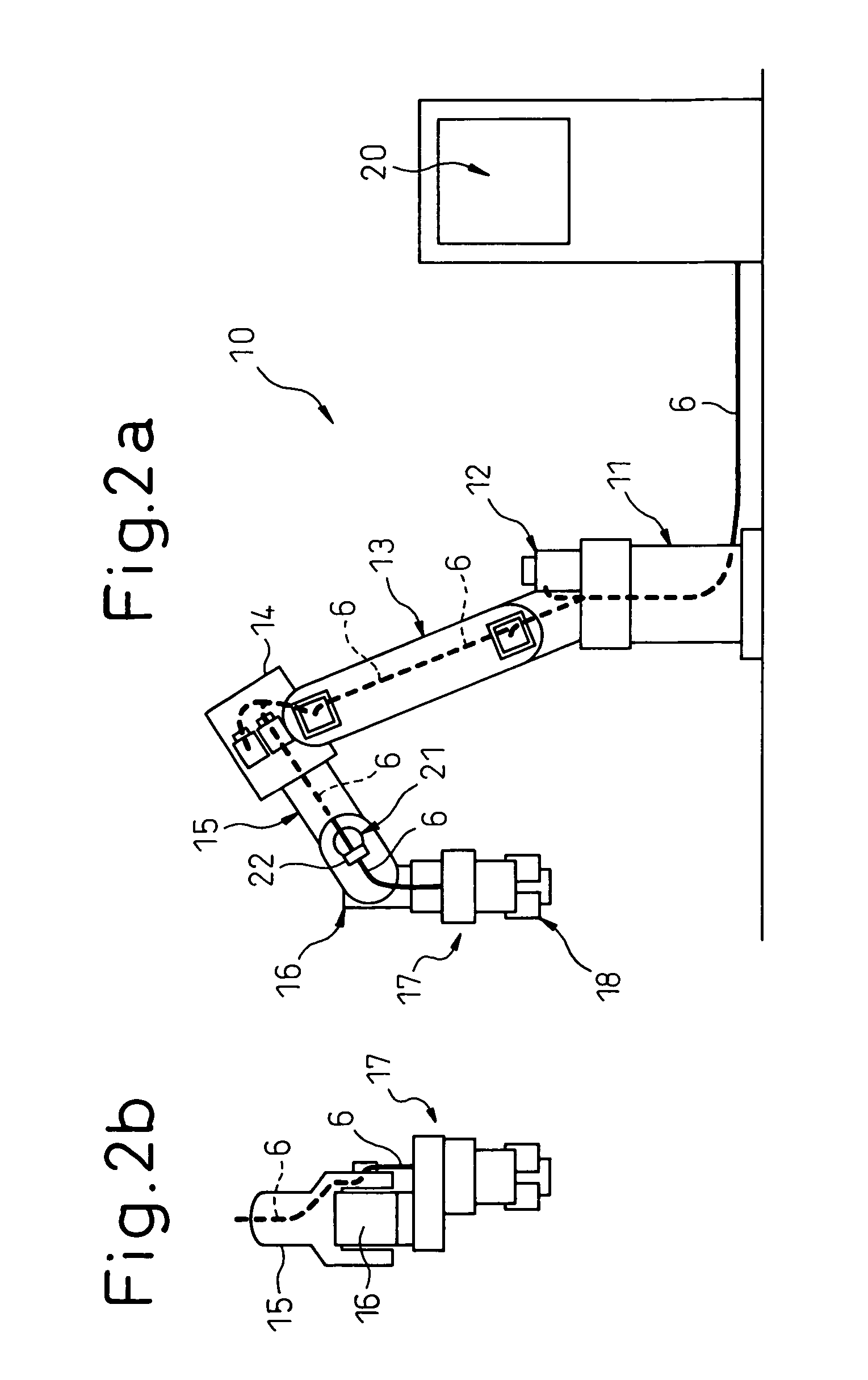
[0026] Embodiments of the invention will be described with reference to FIGS. 2a-7. In a first embodiment, the robot used in the embodiment is a handling robot having a hand as a work tool and an arranged umbilical member is a control cable for the hand. In a second embodiment, the robot used in the embodiment is an arc welding robot having a welding torch as a work tool and an arranged umbilical member includes a wire for welding current, a tube for supplying shielding gas and a liner for supplying a welding wire. However, these embodiments are merely examples.

[0027]FIGS. 2a and 2b show a total configuration of the first embodiment of the invention. In particular, FIG. 2a is a front view and FIG. 2b is a side view showing from a front part of a forearm of the robot to the work tool. In FIG. 2a, a robot 10 is a six-axis robot having a hand 17 attached to the end of a wrist of the robot. The hand 17 may be a conventional hand having gripping jaws 18 and an air cylinder (not shown) f...


PUM


Abstract

A managing structure, for an umbilical member for a work tool of a robot, capable of stabilizing the motion of the umbilical member during the operation of a wrist of the robot and making the work of modifying the system of the robot easier. The umbilical member is introduced into an opening formed at the back of a base of a forearm. The umbilical member extends through a hollow portion of a speed reducer and is drawn from a first opening formed on the side of a first wrist element. A cable for welding current and a tube for supplying shield gas, constituting the umbilical member, are directly connected to a welding torch rotatable about a third axis. A welding wire is guided and fed by a feed roller of a wire feeder and, then, is connected to the welding wire with the cable and the tube. The feed roller is driven by a motor contained within the first wrist element.

Description

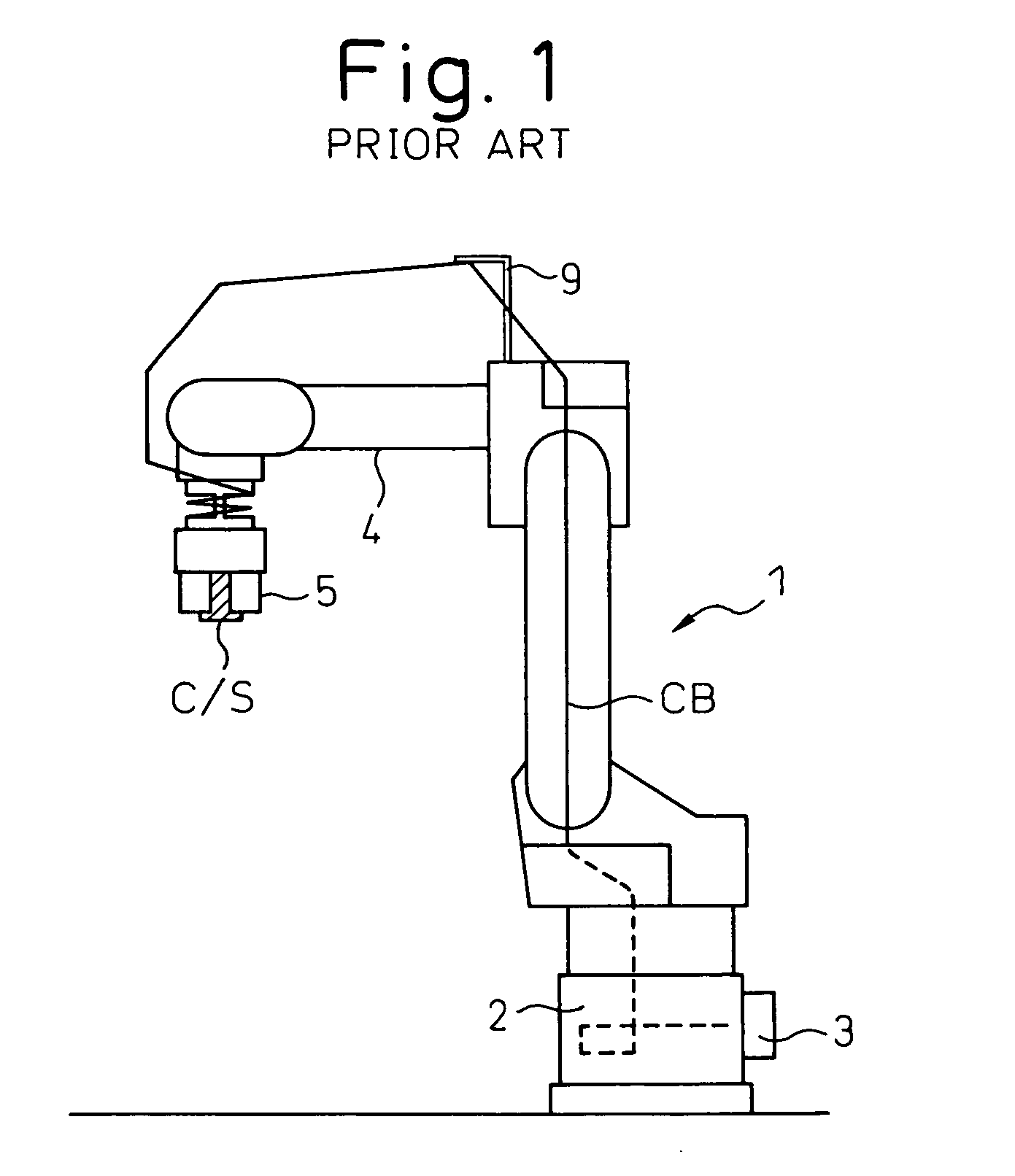
BACKGROUND ART [0001] 1. Technical Field [0002] The preset invention relates to a managing structure for an umbilical member including a cable and / or a tube connected to a work tool, such as a hand or a welding torch, attached to an industrial robot. [0003] 2. Description of the Related Art [0004] Generally, in an industrial robot (hereinafter referred to simply as a robot), a work tool, such as a hand or a welding torch, is attached to an end of a wrist of the robot. Alternatively, a camera or a force sensor may be attached to the end of the wrist of the robot. In this specification, the camera or the sensor attached to the wrist of the robot is also referred as a kind of “a work tool”. Many of the work tools must be supplied with electrical energy, an electrical signal, air, assist gases or a welding wire. Further, a cable and / or a tube are used to supply the work tool. There are many kind of configuration of the cable and / or the tube. For example, a plurality of cables may be col...

Claims


Application Information

Patent Timeline
IPC IPC(8): B25J18/00B25J19/00
CPCY10T74/20305B25J19/0029
Inventor INOUE, TOSHIHIKONAKAYAMA, KAZUTAKAIWAYAMA, TAKATOSHI
Owner FANUC LTD
Learn More