
Depth adjustment mechanism

a technology of depth adjustment and power tools, applied in the field of power tools, can solve the problems of not being able to finely adjust the depth of cut, the adjustment mechanism employed currently may also be limited by its ability to achieve satisfactory, and the operator's fatigue and stress, etc., to achieve the effect of reducing fatigue and stress on the operator, prolonging the use of the router, and improving the adjustment method

Inactive Publication Date: 2006-05-18
BLACK & DECKER INC
View PDF99 Cites 28 Cited by
  • Summary
  • Abstract
  • Description
  • Claims
  • Application Information

AI Technical Summary

Benefits of technology

The present invention is a depth adjustment mechanism for a router that allows for continuous metered depth adjustments. This mechanism can be enabled by a worm drive assembly mounted parallel to a cylindrical portion of a motor casing of the router. The depth adjustment mechanism can be easily accessed by an operator and facilitates easy replacement of bits in the router. The invention provides a more efficient and easy way for operators to adjust the depth of cut performed by the router, which can reduce fatigue and stress on the operator and prolong the use of the router.

Problems solved by technology

Unfortunately, the typical designs have required the use of non-integrated parts to accomplish these depth adjustments.
The adjustment mechanisms employed currently may also be limited by their ability to achieve satisfactory results.
For instance, some adjustment mechanisms may be enabled to satisfactorily achieve coarse adjustments, allowing the operator to make significant changes in the depth of cut to be achieved, but fail to provide a satisfactory ability to fine adjust the depth of cut.
Alternatively, adjustment mechanisms designed to provide fine adjustments may have overly burdensome mechanisms.
For example, some current depth adjustment mechanisms may provide a limited number of predetermined stops which limit the flexibility of cut depth.
This design feature being based on the assumption that totally integrating a depth adjustment mechanism into a router would make the router too large, uncontrollable, or aesthetically displeasing.

Method used


Image

  • Depth adjustment mechanism
  • Depth adjustment mechanism
  • Depth adjustment mechanism

Examples


Embodiment Construction

[0048] Reference will now be made in detail to the presently preferred embodiments of the invention, examples of which are illustrated in the accompanying drawings, FIGS. 1 through 34.

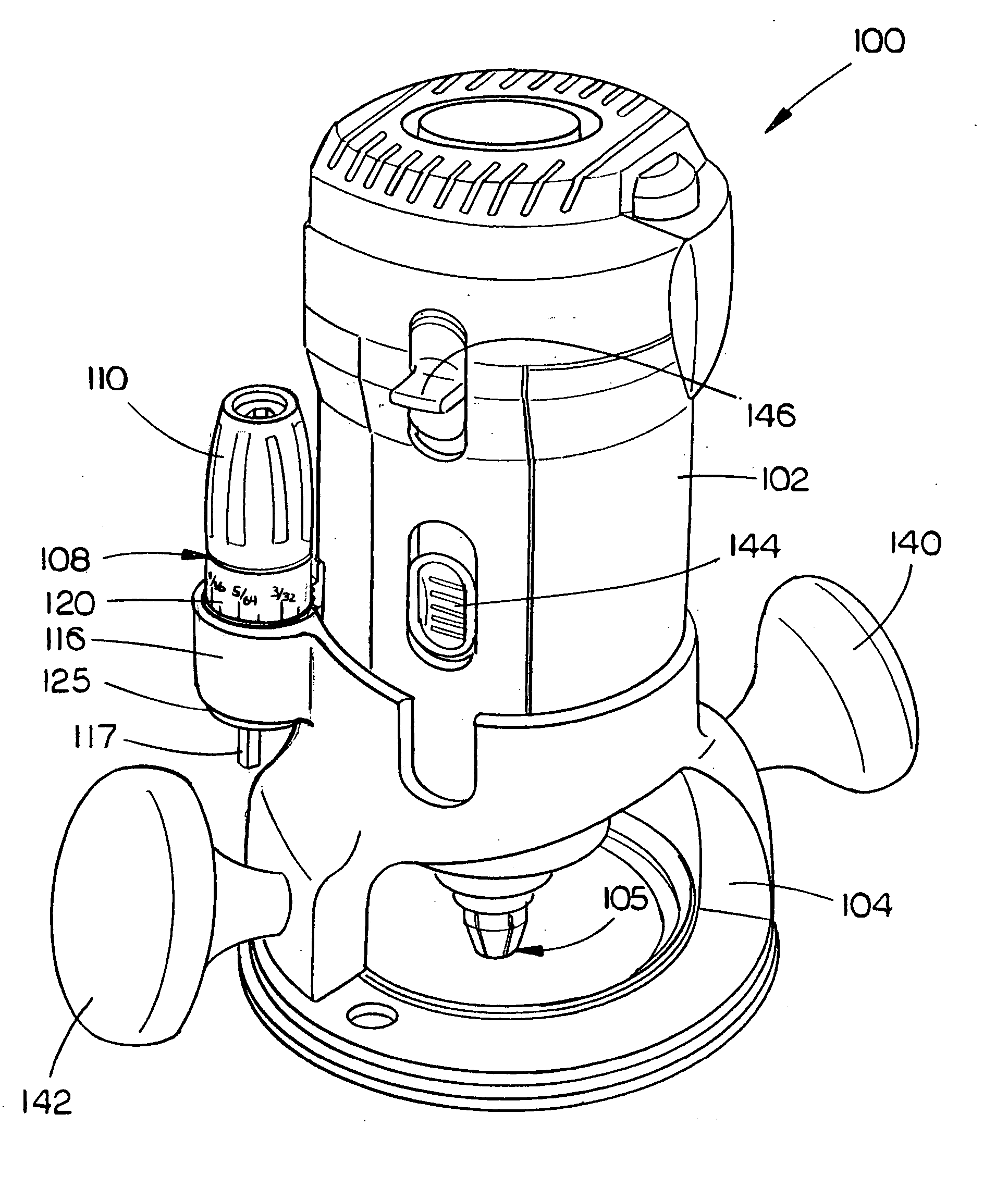
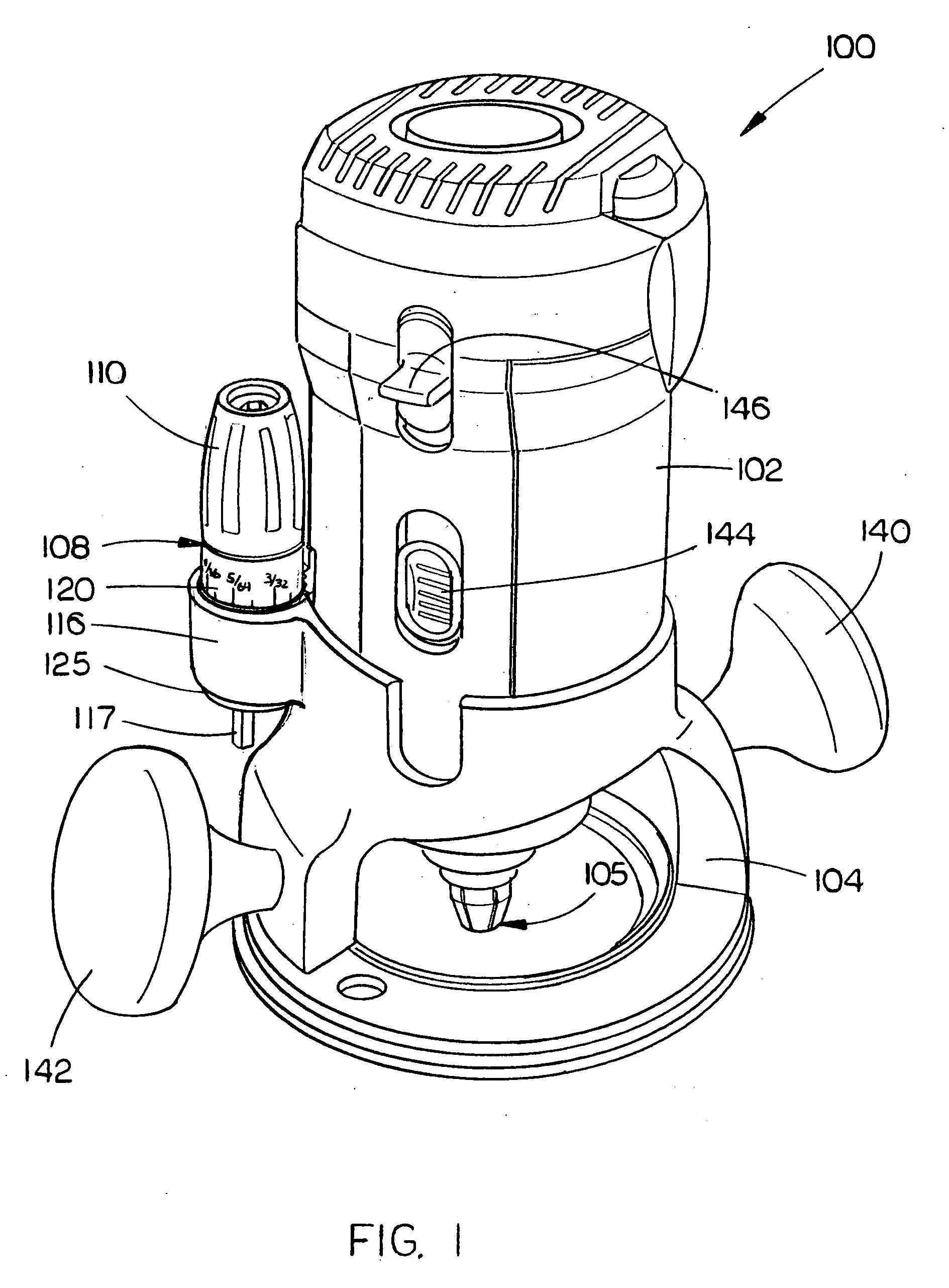
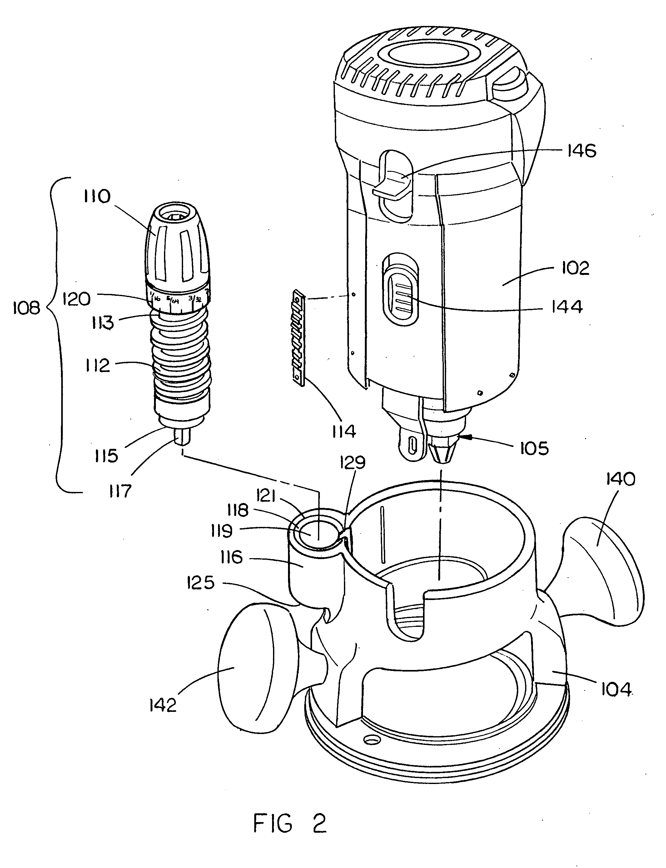
[0049] Referring generally now to FIGS. 1 through 4, a first exemplary embodiment of a router assembly 100 including a motor casing 102 adjustably coupled with a base 104 and a depth adjustment mechanism, is shown. The motor casing 102 is disposed with a motor operationally coupled with a spindle and collet assembly 105 which may operationally couple a router bit. The depth adjustment mechanism is enabled as a worm drive assembly comprising a handle 108 including a rotating member 110 which is operationally coupled with a shaft member 112. In the current embodiment, the shaft member 112 is a shaft member. Various other configurations of the shaft member 112 may be employed without departing from the scope and spirit of the present invention. A first end 113 of the shaft member 112 couples with the rot...


PUM

PropertyMeasurementUnit
depthaaaaaaaaaa
depth adjustmentaaaaaaaaaa
depth of cutaaaaaaaaaa

Abstract

A depth adjustment mechanism, disposed on a router, is enabled using a worm drive that includes a shaft member engaging with a rack member. The shaft member couples with a sleeve disposed on a base of the router. The rack member is coupled with a motor casing of the router. The depth adjustment mechanism enables a user selectable engagement of the shaft member with the rack member. A rotating member, which is coupled with the shaft member, is engaged by a user to displace the shaft member relative to the rack member. The selective engagement of the shaft member with the rack member and rotation enabled by the rotating member enables continuous metered depth adjustment for the router.

Description

CROSS REFERENCE TO RELATED APPLICATION [0001] The present invention is claims priority under 35 U.S.C. §120 as a continuation-in-part of the U.S. application Ser. No. 10 / 686,300, filed on Oct. 15, 2003, which claims priority under 35 U.S.C. §119(e) to the U.S. Provisional Application Ser. No. 60 / 418,510, filed on Oct. 15, 2002, and the U.S. Povisional Application Ser. No. 60 / 467,169, filed May 1, 2003. The U.S. application Ser. No. 10 / 686,300 and both U.S. Provisional Applications 60 / 418,510 and 60 / 467,169 are herein incorporated by reference in their entireties.FIELD OF THE INVENTION [0002] The present invention generally relates to the field of power tools, and particularly to a depth adjustment mechanism for a power tool, such as a router, biscuit joiner, planers, and the like. BACKGROUND OF THE INVENTION [0003] Routers are employed to accomplish a variety of tasks. Used for shaping objects typically composed of wood, plastic, metal, composite materials, and the like, routers hav...

Claims


Application Information

Patent Timeline
Patent Type & Authority Applications(United States)
IPC IPC(8): B27C5/10B27C1/00B23C1/20
CPCB27C5/02B27C5/10Y10T409/306608Y10T409/307952Y10T409/30672
Inventor COOPER, RANDY G.ETTER, MARK A.GRIFFIN, GREG K.ALLEN, GINGER L.KILBOURNE, DERRICK
Owner BLACK & DECKER INC
Learn More