Internal riser rotating control head

Inactive Publication Date: 2006-05-18
WEATHERFORD TECH HLDG LLC
View PDF73 Cites 71 Cited by
  • Summary
  • Abstract
  • Description
  • Claims
  • Application Information

AI Technical Summary

Benefits of technology

[0022] In one embodiment, a pressure relief assembly allows relieving excess pressure within the borehole. In a further embodiment, a

Problems solved by technology

During some operations, gas can unintentionally enter the riser from the wellbore.
However, diverters are not used during normal drilling operations and are generally only activated when indications of gas in the riser are observed.
U.S. Pat. No. 6,263,982 proposes an underbalanced drilling concept of using a rotating control head to seal a marine riser while drilling in the floor of an ocean using a rotatable pipe from a floating structure.
The wireline operation system of the '289 patent does not teach, suggest or provide any motivation for use a rotating control head, much less teach, suggest, or provide any motivation for sealing an annular blowo

Method used


Image

  • Internal riser rotating control head
  • Internal riser rotating control head
  • Internal riser rotating control head

Examples


Embodiment Construction

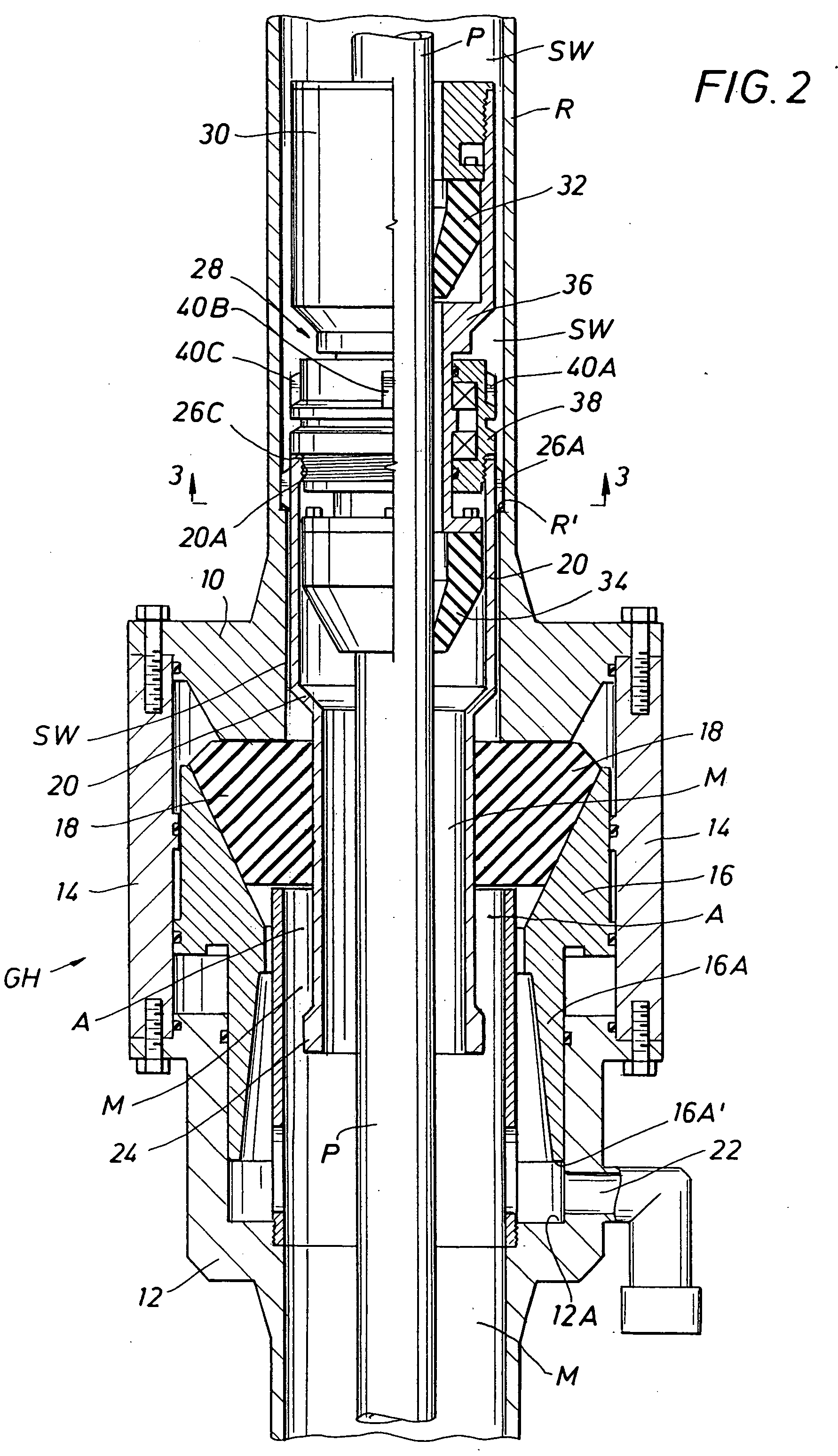
[0074] Turning to FIG. 2, the riser or upper tubular R is shown positioned above a gas handler annular blowout preventer, generally designated as GH. While a “HYDRIL” GH 21-2000 gas handler BOP or a “HYDRIL” GL series annular blowout handler could be used, ram type blowout preventers, such as Cameron U BOP, Cameron UII BOP or a Cameron T blowout preventer, available from Cooper Cameron Corporation of Houston, Tex., could be used. Cooper Cameron Corporation also provides a Cameron DL annular BOP. The gas handler annular blowout preventer GH includes an upper head 10 and a lower body 12 with an outer body or first or subsea housing 14 therebetween. A piston 16 having a lower wall 16A moves relative to the first housing 14 between a sealed position, as shown in FIG. 2, and an open position, where the piston moves downwardly until the end 16A′ engages the shoulder 12A. In this open position, the annular packing unit or seal 18 is disengaged from the internal housing 20 of the present in...


PUM


Abstract

A holding member provides for releasably positioning a rotating control head assembly in a subsea housing. The holding member engages an internal formation in the subsea housing to resist movement of the rotating control head assembly relative to the subsea housing. The rotating control head assembly is sealed with the subsea housing when the holding member engages the internal formation. An extendible portion of the holding member assembly extrudes an elastomer between an upper portion and a lower portion of the internal housing to seal the rotating control head assembly with the subsea housing. Pressure relief mechanisms release excess pressure in the subsea housing and a pressure compensation mechanism pressurize bearings in the bearing assembly at a predetermined pressure.

Description

CROSS-REFERENCE TO RELATED APPLICATIONS [0001] This application is a divisional of U.S. application Ser. No. 10 / 281,534, entitled “Internal Riser Rotating Control Head,” filed Oct. 28, 2002, which is a continuation-in-part of U.S. application Ser. No. 09 / 516,368, entitled “Internal Riser Rotating Control Head,” filed Mar. 1, 2000, which issued as U.S. Pat. No. 6,470,975 on Oct. 29, 2002, and which claims the benefit of and priority to U.S. Provisional Application Serial No. 60 / 122,530, filed Mar. 2, 1999, entitled “Concepts for the Application of Rotating Control Head Technology to Deepwater Drilling Operations,” all of which are hereby incorporated by reference in their entirety for all purposes.STATEMENTS REGARDING FEDERALLY SPONSORED RESEARCH OR DEVELOPMENT [0002] Not applicable. REFERENCE TO A MICROFICHE APPENDIX [0003] Not applicable. BACKGROUND OF THE INVENTION [0004] 1. Field of the Invention [0005] The present invention relates to drilling subsea. In particular, the present ...

Claims


Application Information

Patent Timeline
IPC IPC(8): E21B15/02E21B21/00E21B21/08E21B33/08
CPCE21B2021/006E21B23/006E21B21/08E21B21/001E21B33/085E21B21/085E21B33/064E21B33/08
Inventor BOURGOYNE, DARRYL A.HANNEGAN, DON M.BAILEY, THOMAS F.CHAMBERS, JAMES W.WILSON, TIMOTHY L.
Owner WEATHERFORD TECH HLDG LLC
Why Eureka
Try Eureka