[0016] Due to the pressure fluctuations in the housing, the movable cleaning member is thrown or hurled back and forth in the chamber. The striking or impact of the cleaning member, for example against the inner wall of the housing or against a spark arrestor, loosens the particles that have accumulated on the wall or have adhered thereto. These loosened particles are then conveyed out of the muffler together with the exhaust gases. The cleaning member thus continuously effects an automatic or self cleaning of the muffler. The cleaning member can have a simple construction as well as a low weight, so that in particular in manually guided implements the overall weight of the implement is not noticeably affected. The sound that results when the cleaning member strikes against a wall can, by suitable selection of the cleaning member, be balanced such that the generation of noise is minimal relative to the operating noise of the internal combustion engine.
[0017] A straightforward design results if the cleaning member is freely movable in the chamber. By means of suitable selection of the inner geometry of the chamber, and the outer geometry of the cleaning member, it is possible to completely clean the chamber with the cleaning member. However, it can also be advantageous to guide the cleaning member with play in the chamber. In particular, the cleaning member can be arranged in such a way that it cleans regions that are particularly susceptible to being fouled. The outer surface of the cleaning member is advantageously guided with play against the inner wall of the chamber.
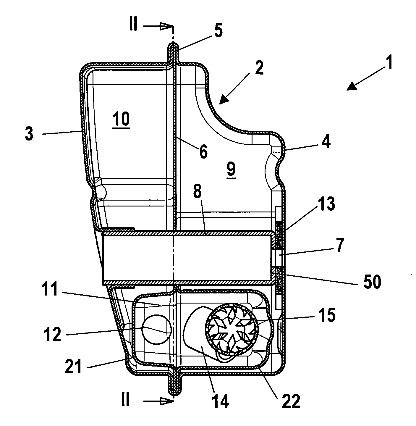
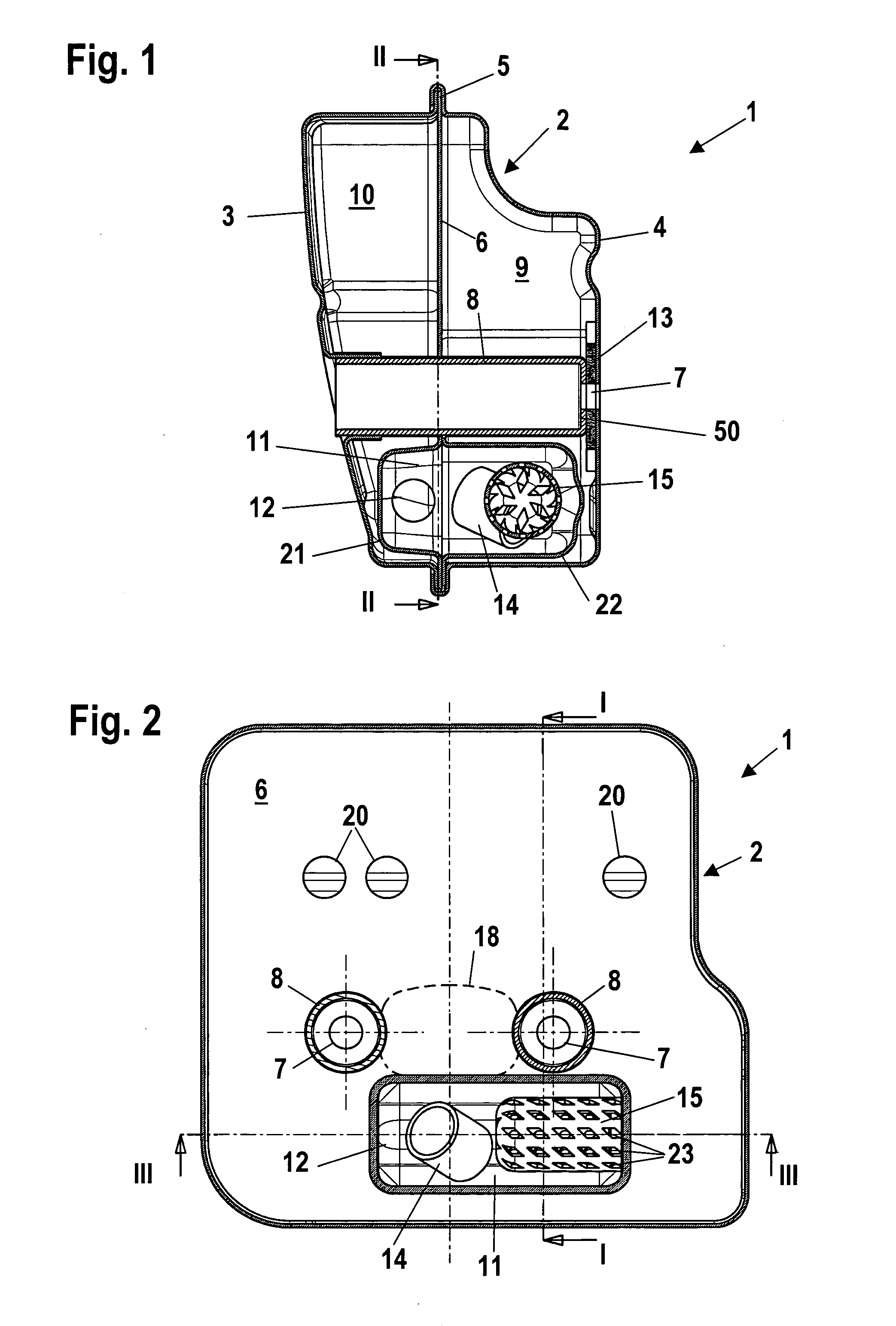
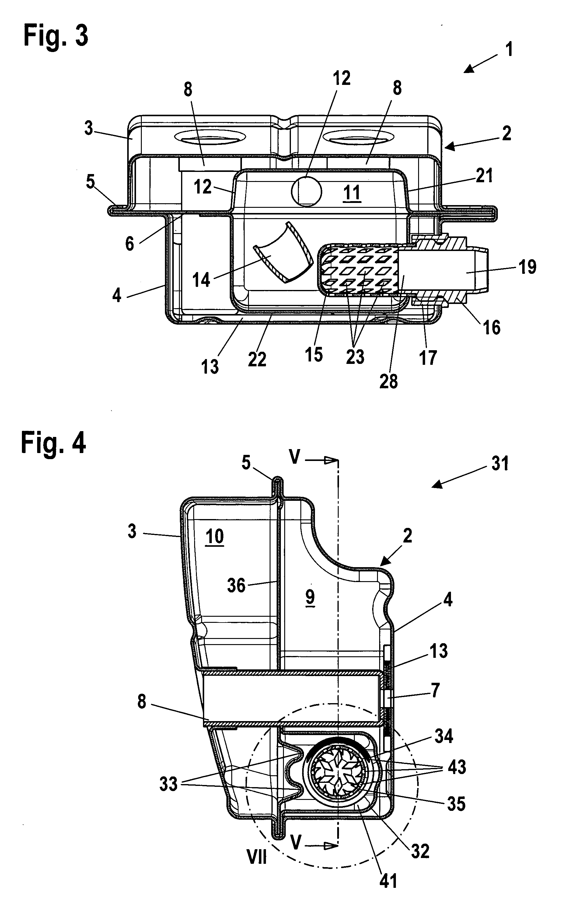
[0018] To prevent discharge of glowing particles from the muffler, and to satisfy local regulations, a spark arrestor is disposed at the outlet out of the chamber. By disposing the cleaning member in the chamber in which the spark arrestor is disposed, fouling of the spark arrestor can be reduced. The spark arrestor is in particular cylindrical, and the cleaning member is advantageously guided with play on the periphery of the spark arrestor. During operation of the muffler, dirt particles can easily accumulate or adhere to the spark arrestor. To prevent clogging of the spark arrestor, it must be replaced on a regular basis. By disposing a cleaning member on the spark arrestor, dirt particles are continuously removed from the spark arrestor during operation, so that the maintenance intervals can be considerably increased.
[0019] The cleaning member is in particular supported between the chamber wall and the spark arrestor. The play relative to the inner wall of the chamber is advantageously greater than the play relative to the spark arrestor. Thus, during operation, the cleaning member preferably strikes against the spark arrestor and cleans it. If the vibrations are strong, the inner wall of the chamber forms a stop or abutment for the cleaning member, so that the spark arrestor cannot be deformed or destroyed by the cleaning member. The cleaning member is advantageously movable in a peripheral direction relative to the spark arrestor. It can be advantageous for the cleaning member to be movable in the axial direction of the spark arrestor. The cleaning member is in particular movable not only in the axial direction but also in the peripheral direction relative to the spark arrestor.
[0020] A straightforward embodiment results if the cleaning member is a coil spring. The corrugated structure of the coil spring formed by the spring windings leads to a good loosening or removal of dirt particles. However, it can also be expedient for the cleaning member to be a ring. This ring is advantageously provided with a slot. The cleaning member is advantageously also provided with at least one opening or aperture. The slot or aperture or apertures improve the cleaning effect of the member. If the slot is large enough, it is also possible to mount the cleaning member on the spark arrestor in the radial direction relative to the spark arrestor.
[0021] The housing of the muffler is advantageously formed from two half shells between which is disposed a partition that separates a first chamber from a second chamber. A catalytic converter can in particular be disposed in the partition. A third half shell is advantageously disposed on the partition and forms a third chamber with the partition. Disposing a plurality of chambers one after the other leads to a good dampening effect of the muffler. By connecting the third half shell to the partition, the third chamber can be easily formed with few additional components. The spark arrestor is in particular disposed at the outlet out of the third chamber. In this connection, the outlet out of the third chamber advantageously opens into the outlet out of the muffler.

