
Footwear covert alarm and locator apparatus

Inactive Publication Date: 2006-05-18
FELE HLDG
View PDF17 Cites 60 Cited by
  • Summary
  • Abstract
  • Description
  • Claims
  • Application Information

AI Technical Summary

Benefits of technology

[0025] The present invention relates generally to footwear and, more specifically, to footwear having an alarm circuit that can be selectively engaged by the user to transmit a coded signal to a monitoring authority. The alarm circuit is comprised of circuit board, battery, processor, switch and wiring. The alarm circuit further includes a global positioning system (GPS) for sending location data to the monitoring authority. The alarm circuit is selectively operable via a covered switch for preventing false alarms. The cover can serve as camouflage rendering switch location variable and covert.
[0033] Still another object of the present invention is to provide an alarm circuit for footwear wherein the activation switch cover serves as camouflage, rendering the switch location variable and covert.
[0042] Yet a further object of the present invention is to provide an alarm for footwear wherein the monitoring center is able to selectively notify an emergency or rescue unit.
[0046] The present invention overcomes the shortcomings of the prior art by providing footwear having an alarm circuit that can be selectively activated by the user to transmit a predetermined alarm signal to a monitoring authority. The alarm circuit is comprised of circuit board, battery, processor, activation switch and wiring. The present invention provides for an additional element in the form of GPS location determination receiver that can be used to send location data to a monitoring unit. Inclusion of a switch cover prevents accidental activations. It an also serves as camouflage, rendering the switch location variable and covert. The switch cover can be hinged like a flap using hook and loop material to maintain a closed and inconspicuous means of access. The cover can also incorporate some rigidity or structure to prevent activation of the switch by pressing on the cover.

Problems solved by technology

The apparatus uses a small transmitter that is always carried by the child and as such, is always present when danger arises.
The use of a self contained generator simplifies the construction and obviates the disadvantages associated with battery operated systems of remembering to switch the apparatus on and off and checking the charge status of the batteries to avoid false alarms.

Method used


Image

  • Footwear covert alarm and locator apparatus
  • Footwear covert alarm and locator apparatus
  • Footwear covert alarm and locator apparatus

Examples


Embodiment Construction

[0078] The following discussion describes in detail one embodiment of the footwear alarm and locator apparatus (and several variations of that embodiment). This discussion should not be construed, however, as limiting the invention to those particular embodiments, practitioners skilled in the art will recognize numerous other embodiments as well. For definition of the complete scope of the invention, the reader is directed to appended claims.

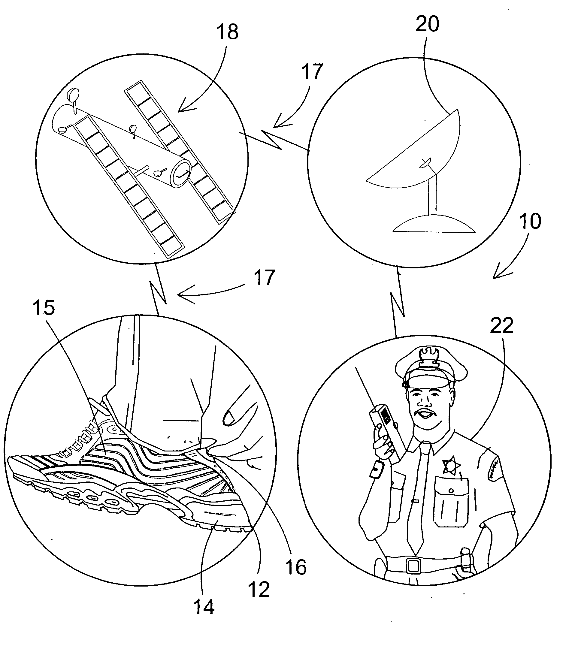
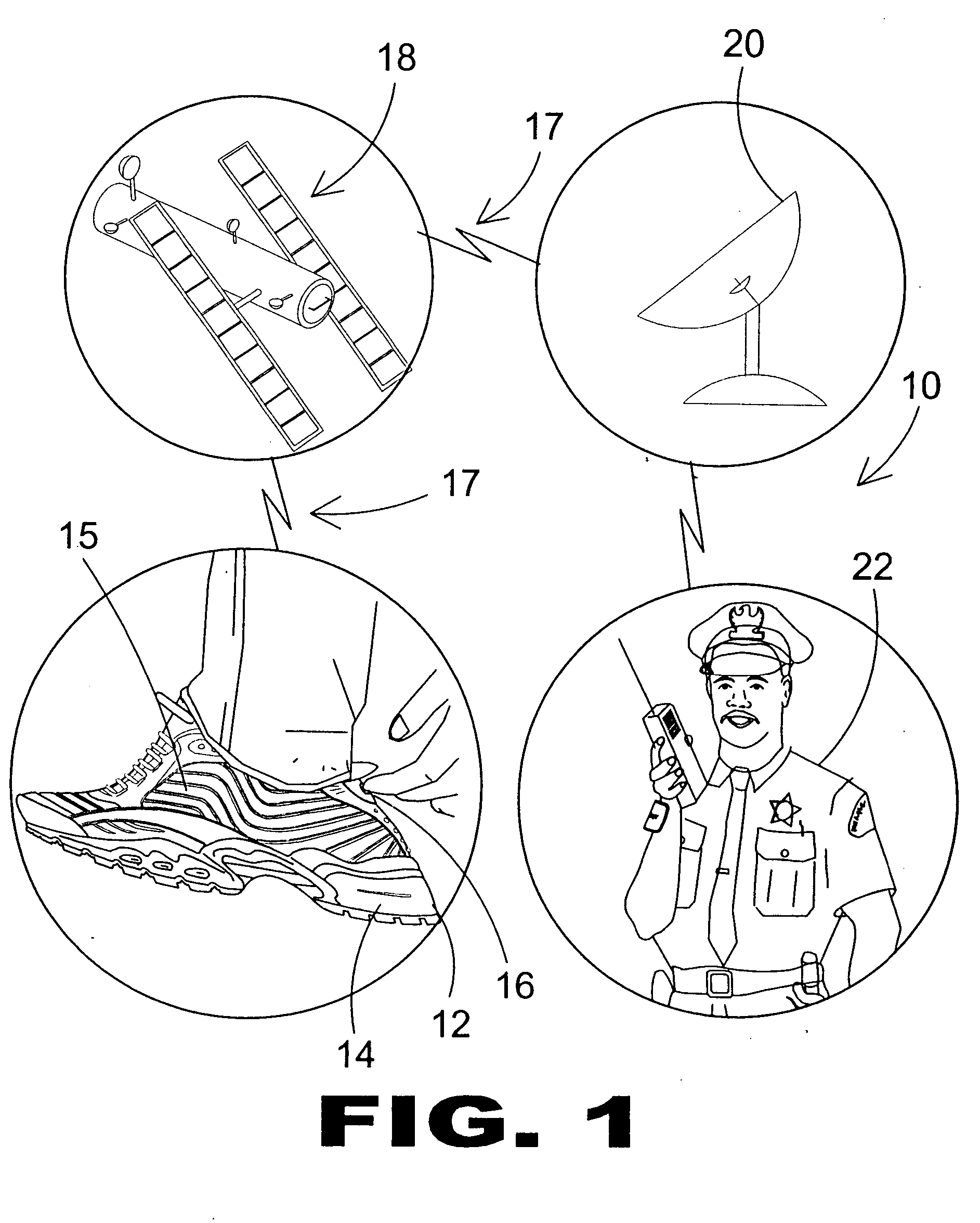
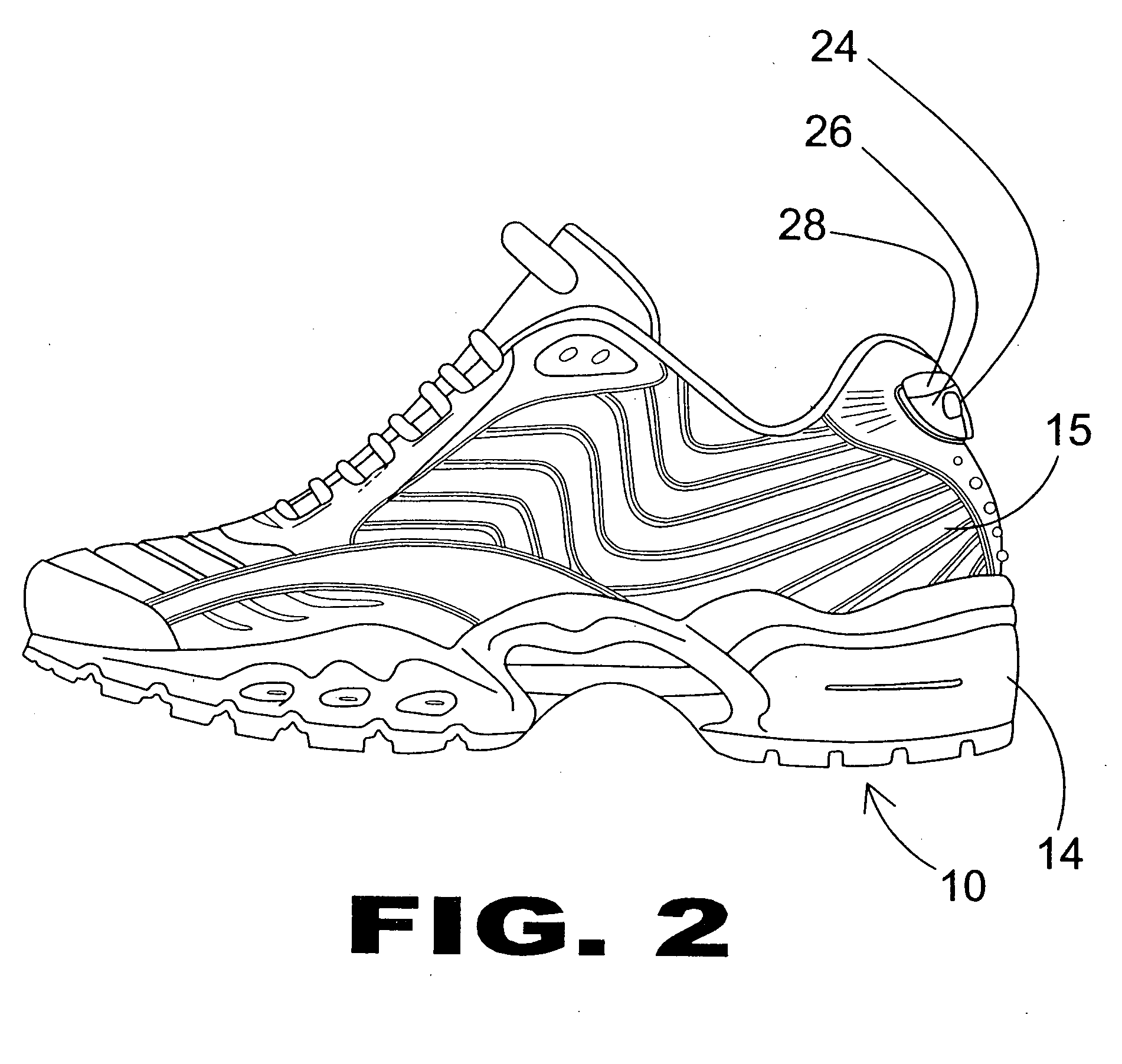
[0079] Turning now descriptively to the drawings, in which similar reference characters denote similar elements throughout the several views, FIGS. 1 through 7 illustrate the footwear alarm of the present invention indicated generally by the numeral 10.

[0080]FIG. 1 is an illustrative view of the footwear alarm and locator apparatus of the present invention. The present invention is a personal location protection system for providing a global positioning system in an article of footwear that is designed to protect the wearer. The footwear alarm...


PUM


Abstract

An alarm apparatus for footwear wherein the footwear includes a sole and a boot connected to the sole thereof. An alarm circuit for generating an alarm signal is positioned within and concealed by the sole of the footwear. An activation switch is positioned on an exterior surface of the boot and is electrically connected to the alarm circuit. Means for transmitting the alarm signal is connected to the alarm circuit. Upon activation of the alarm switch, the alarm signal is generated by the alarm circuit and transmitted by the transmitting means for receipt at a remote location thereby notifying a remote user that a local user is in distress.

Description

BACKGROUND OF THE INVENTION [0001] 1. Field of the Invention [0002] The present invention relates generally to footwear and, more specifically, to footwear having an alarm circuit that can be selectively engaged by the user to transmit a coded signal to a monitoring authority. The alarm circuit is comprised of circuit board, battery, processor, switch and wiring. The alarm circuit further includes a global positioning system (GPS) for sending location data to the monitoring authority. The alarm circuit is selectively operable via a covered switch for preventing false alarms. The cover can serve as camouflage rendering switch location variable and covert. [0003] 2. Description of the Prior Art [0004] There are other alarm device designed for articles. Typical of these is U.S. Pat. No. 1,658,848 issued to Kalikow on Feb. 14, 1928. [0005] Another patent was issued to Kalikow et al on Jul. 22, 1930 as U.S. Pat. No. 1,771,258. Yet another U.S. Pat. No. 3,777,086 was issued to Riedo on De...

Claims


Application Information

Patent Timeline
IPC IPC(8): G08B13/00G08B1/08G01S19/35
CPCA43B3/00A43B3/0005G08B25/016A43B3/34
Inventor DANIEL, SAYO ISAAC
Owner FELE HLDG
Features
  • Generate Ideas
  • Intellectual Property
  • Life Sciences
  • Materials
  • Tech Scout
  • Unparalleled Data Quality
  • Higher Quality Content
  • 60% Fewer Hallucinations
Learn More