[0006] In this type of background device, a mirror is usually supported by a torsion bar (i.e., a hinge). The mirror is driven by changing an electrical potential (hereinafter referred to as potential) of the mirror. A larger
deflection angle can be obtained in a bi-directional operation of the mirror than in a mono-stable operation. To obtain bi-stability, a hinge of relative
high stiffness is used for the mirror in the background device. In driving the mirror, therefore, the potential of the mirror and potentials of electrodes opposite to the mirror are simultaneously changed.
[0006] In this type of background device, a mirror is usually supported by a torsion bar (i.e., a hinge). The mirror is driven by changing an electrical potential (hereinafter referred to as potential) of the mirror. A larger deflection angle can be obtained in a bi-directional operation of the mirror than in a mono-stable operation. To obtain bi-stability, a hinge of relative high stiffness is used for the mirror in the background device. In driving the mirror, therefore, the potential of the mirror and potentials of electrodes opposite to the mirror are simultaneously changed.
[0006] In this type of background device, a mirror is usually supported by a torsion bar (i.e., a hinge). The mirror is driven by changing an electrical potential (hereinafter referred to as potential) of the mirror. A larger deflection angle can be obtained in a bi-directional operation of the mirror than in a mono-stable operation. To obtain bi-stability, a hinge of relative high stiffness is used for the mirror in the background device. In driving the mirror, therefore, the potential of the mirror and potentials of electrodes opposite to the mirror are simultaneously changed.
[0006] In this type of background device, a mirror is usually supported by a torsion bar (i.e., a hinge). The mirror is driven by changing an electrical potential (hereinafter referred to as potential) of the mirror. A larger deflection angle can be obtained in a bi-directional operation of the mirror than in a mono-stable operation. To obtain bi-stability, a hinge of relative high stiffness is used for the mirror in the background device. In driving the mirror, therefore, the potential of the mirror and potentials of electrodes opposite to the mirror are simultaneously changed.
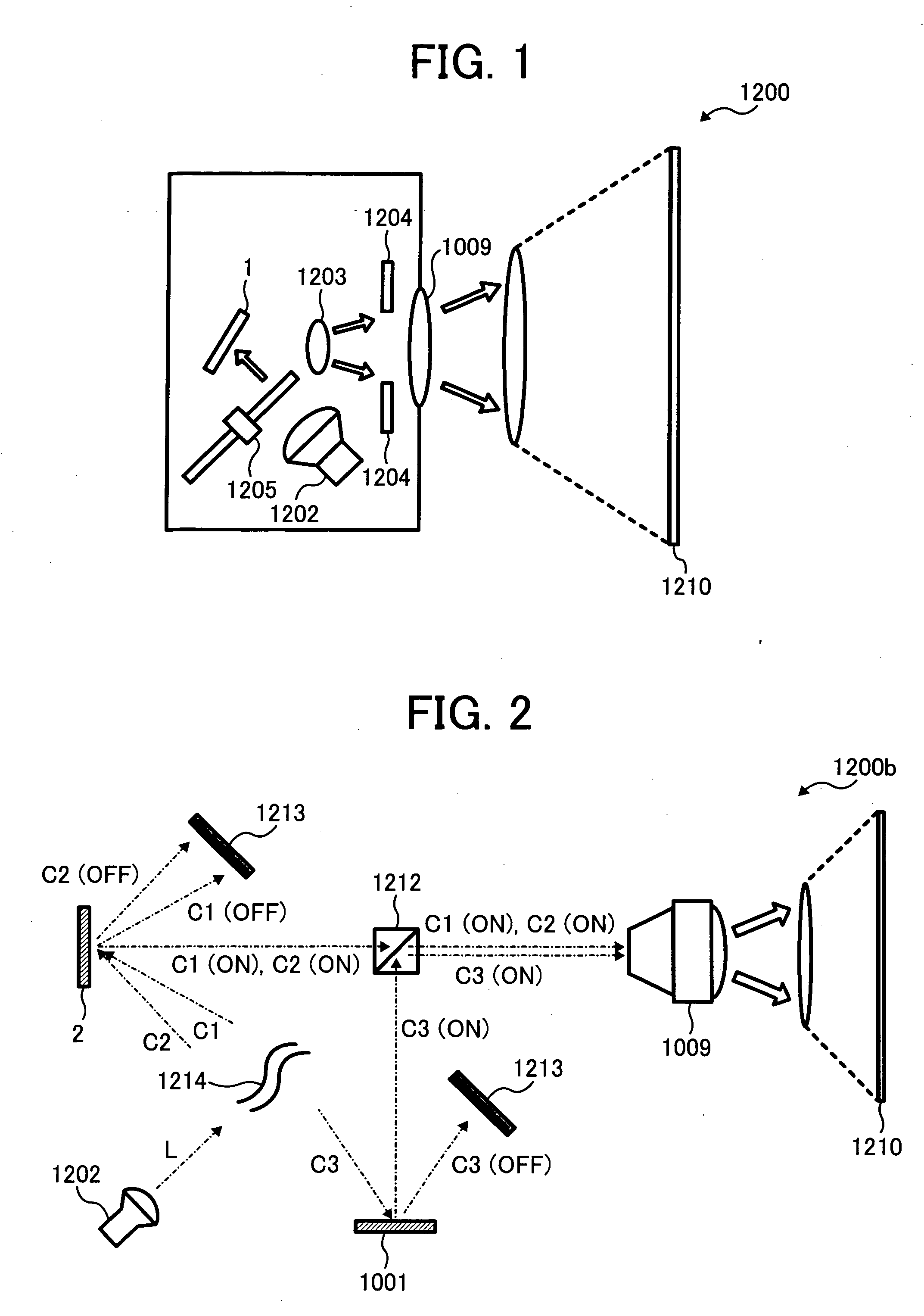
[0003] The present invention relates to an optical deflection device and an image
projection display apparatus using the optical deflection device, and more particularly to an optical deflection device and an image projection display apparatus capable of performing an optical deflection operation in four directions along two axes.
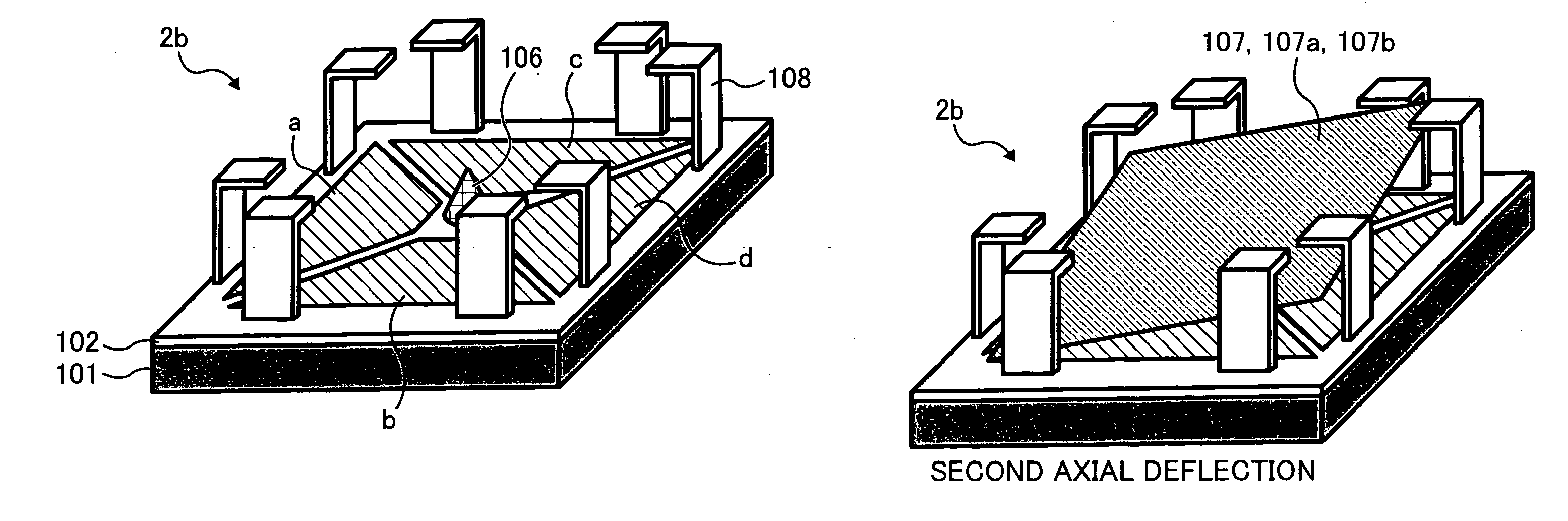
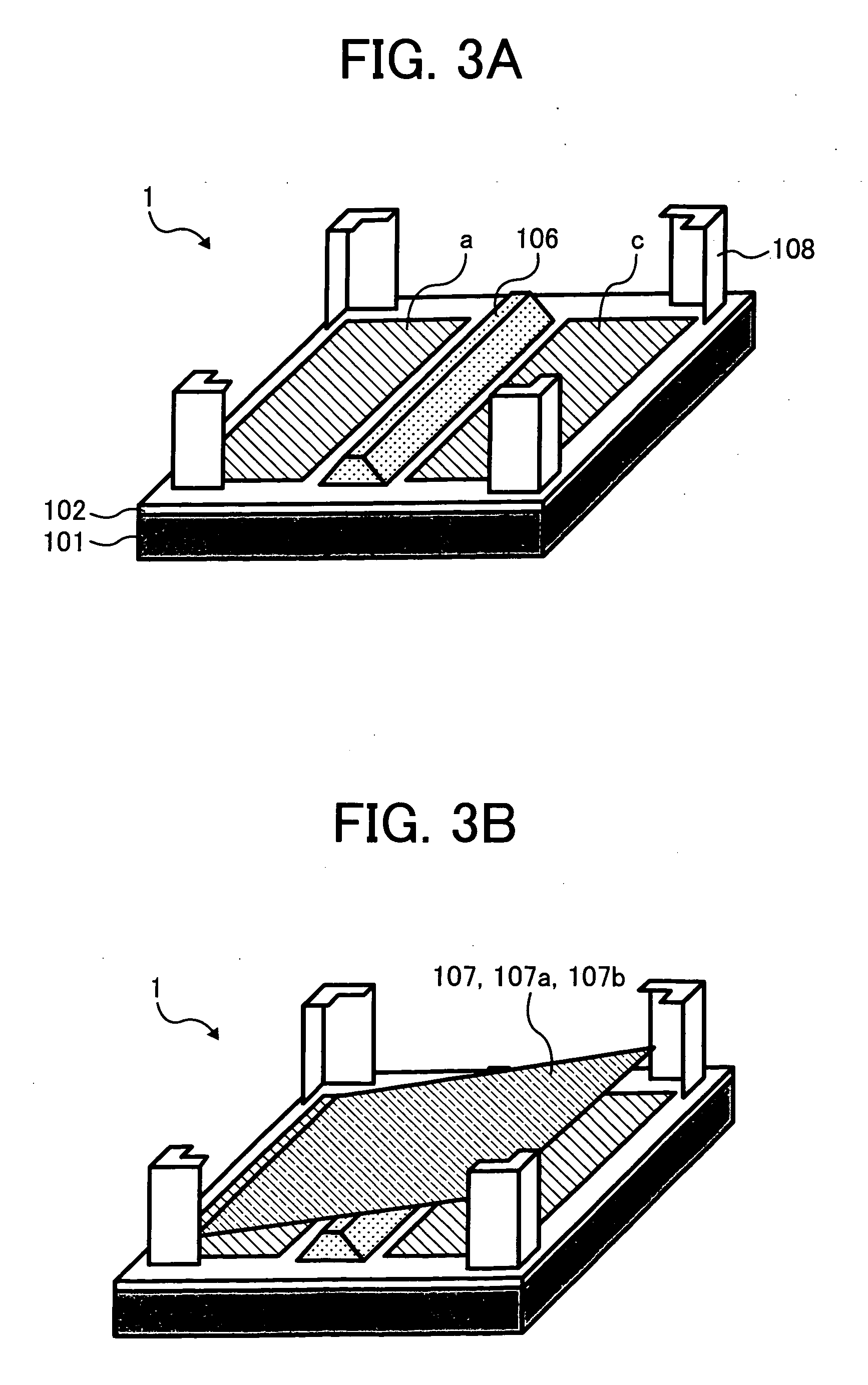
[0008] This patent specification describes a novel optical deflection device. In one aspect, a novel optical deflection device includes a substrate, a plurality of regulating members, a fulcrum member, a plate member, and a plurality of electrodes. The plurality of regulating members are respectively provided at a plurality of edge portions on an upper surface of the substrate, and respectively include upper portions including stoppers. The fulcrum member is provided on the upper surface of the substrate, and includes a top portion serving as an
electrode configured to establish a potential thereof. The plate member is movably placed in a space formed by the substrate, the fulcrum member, and the stoppers. The plate member includes unfixed edge portions, a light reflecting region forming an upper surface of the plate member, and a conductive layer electrically connected to the fulcrum member. The plurality of electrodes are provided on the upper surface of the substrate to be approximately opposite to the conductive layer of the plate member and to surround the fulcrum member. When at least a part of the plurality of electrodes are fixed to predetermined potentials and a potential of the fulcrum member is changed, the plate member tilts and displaces around the fulcrum member due to
electrostatic attraction force, and a light incident in the light reflecting region in a first direction is deflected and reflected in a second direction different from the first direction.
[0006] In this type of background device, a mirror is usually supported by a torsion bar (i.e., a hinge). The mirror is driven by changing an electrical potential (hereinafter referred to as potential) of the mirror. A larger deflection angle can be obtained in a bi-directional operation of the mirror than in a mono-stable operation. To obtain bi-stability, a hinge of relative high stiffness is used for the mirror in the background device. In driving the mirror, therefore, the potential of the mirror and potentials of electrodes opposite to the mirror are simultaneously changed.
[0006] In this type of background device, a mirror is usually supported by a torsion bar (i.e., a hinge). The mirror is driven by changing an electrical potential (hereinafter referred to as potential) of the mirror. A larger deflection angle can be obtained in a bi-directional operation of the mirror than in a mono-stable operation. To obtain bi-stability, a hinge of relative high stiffness is used for the mirror in the background device. In driving the mirror, therefore, the potential of the mirror and potentials of electrodes opposite to the mirror are simultaneously changed.
[0058] The lens-mirror
system 1214 (indicated by wave lines in FIG. 2 for simplification) includes a plurality of optical mirrors and lenses. The lens-mirror
system 1214 applies the light L emitted from the
light source 1202 to the optical deflection devices 1 and 2 as incident light fluxes C1, C2, and C3. The incident light fluxes C1, C2, and C3 are of different colors from one another (i.e., the three primary colors red, green, and blue). Alternatively, the incident light fluxes C1, C2, and C3 may be other colors different from the three primary colors having different wavelengths.
[0006] In this type of background device, a mirror is usually supported by a torsion bar (i.e., a hinge). The mirror is driven by changing an electrical potential (hereinafter referred to as potential) of the mirror. A larger deflection angle can be obtained in a bi-directional operation of the mirror than in a mono-stable operation. To obtain bi-stability, a hinge of relative high stiffness is used for the mirror in the background device. In driving the mirror, therefore, the potential of the mirror and potentials of electrodes opposite to the mirror are simultaneously changed.
[0005] A digital micro-mirror device including a torsion bar hinge has been proposed by L. J. Hornbeck. The digital micro-mirror device is developed into a
spatial light modulator which includes a group of micro mirrors. The spatial light modulator is referred to as a DMD (digital micro-mirror device) and is used in image projection display apparatuses, for example.

