Optical scanning apparatus and image forming apparatus provided with the same

a technology of optical scanning apparatus and image forming apparatus, which is applied in the direction of optical elements, instruments, optical radiation measurement, etc., can solve the problems of high accuracy and cost, high cost, and high cost of scanning position sensor, and achieve the effect of increasing cos

Inactive Publication Date: 2011-05-05
KYOCERA DOCUMENT SOLUTIONS INC
View PDF8 Cites 5 Cited by
  • Summary
  • Abstract
  • Description
  • Claims
  • Application Information

AI Technical Summary

Benefits of technology

[0018]However, the techniques proposed in Japanese Patent Application Publications Nos. H1-100509, H3-134613, 2004-029064, and 2006-047590 have a problem of complex configuration and control leading to a higher cost.

Problems solved by technology

H1-100509, H3-134613, 2004-029064, and 2006-047590 have a problem of complex configuration and control leading to a higher cost.
H1-100509 requires a high-accuracy and expensive scanning position sensor for scanning in both directions.
In addition, the technique proposed in Japanese Patent Application Publication No. 2004-029064 requires a complex control for detecting a weak induced current.
To realize this, a complex and expensive drive circuit is necessary.
Even by limiting the variable range of voltage by selecting a MEMS mirror with a resonance frequency, there are problems of a decreased yield rate and an increased cost of the MEMS mirror.

Method used


Image

  • Optical scanning apparatus and image forming apparatus provided with the same
  • Optical scanning apparatus and image forming apparatus provided with the same
  • Optical scanning apparatus and image forming apparatus provided with the same

Examples


first embodiment

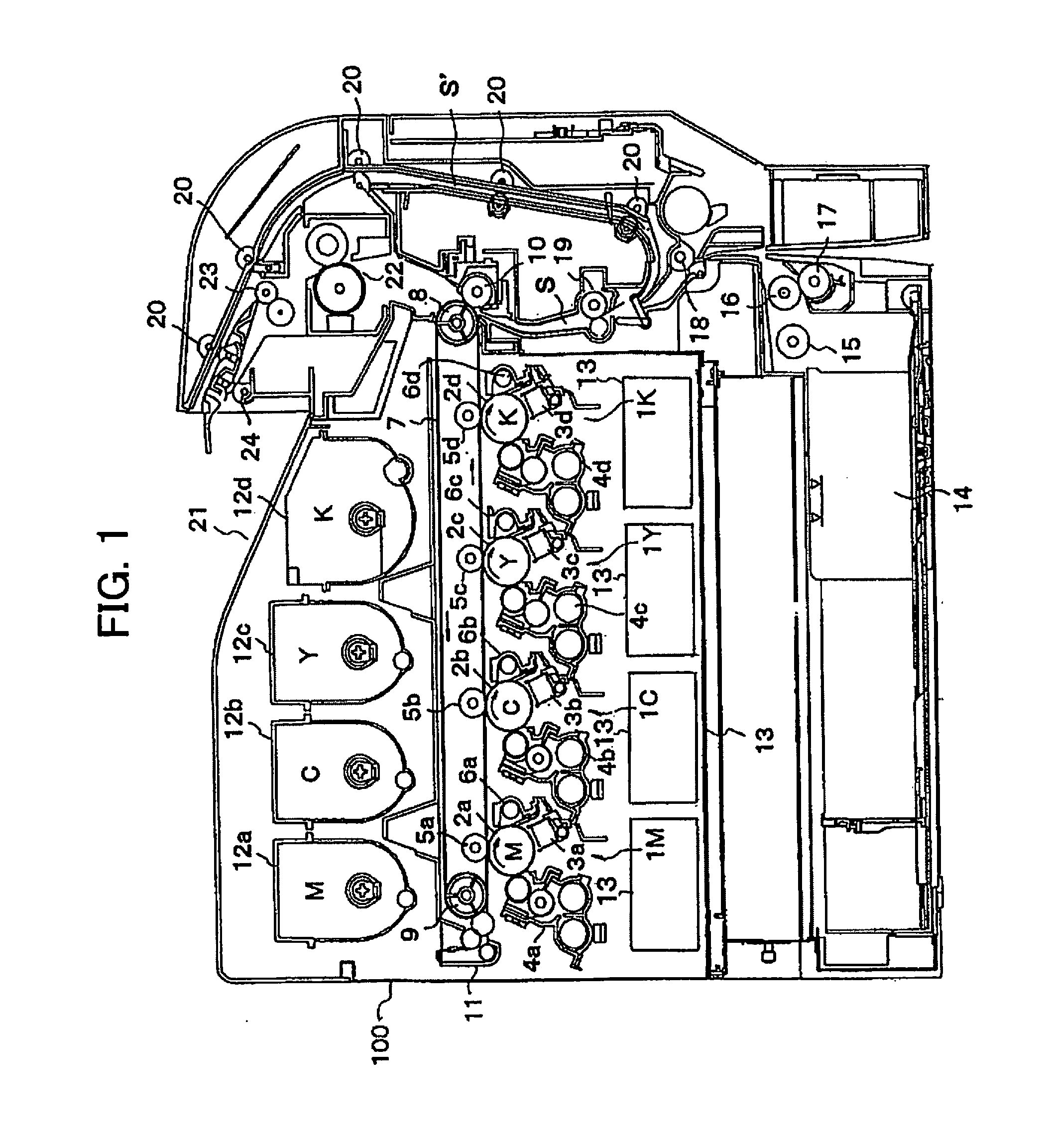
[0042]FIG. 1 is a cross-sectional view of a color laser printer as an image forming apparatus according to the present invention. The color laser printer shown is of a tandem system. In a central portion inside a main body 100 of the color laser printer, a magenta image forming unit 1M, a cyan image forming unit 1C, a yellow image forming unit 1Y, and a black image forming unit 1K are arranged in tandem at constant intervals.

[0043]In the abovementioned image forming units 1M, 1C, 1Y and 1K, photoreceptor drums 2a, 2b, 2c, and 2d, which are image carrying body, are respectively disposed. In a periphery of each of the photoreceptor drums 2a, 2b, 2c and 2d, charging devices 3a, 3b, 3c and 3d, developing devices 4a, 4b, 4c and 4d, transfer rollers 5a, 5b, 5c and 5d, and drum cleaning devices 6a, 6b, 6c and 6d are respectively disposed.

[0044]Here, the abovementioned photoreceptor drums 2a, 2b, 2c and 2d are drum-shaped photoreceptors that are rotationally driven at a predetermined proces...

second embodiment

[0085]In the second embodiment, the MEMS mirror 36 is driven at a constant cycle by a drive unit (AC power source), which is controlled by a drive control unit. The drive control unit includes: a first control portion that coarsely adjusts the maximum deflection angle of the MEMS mirror 36 by variance control of amplitude of the drive control signal while maintaining a basic cycle of a drive signal of the drive control unit; and a second control portion that finely adjusts the maximum deflection angle of the MEMS mirror 36 by variance control of waveform of the drive control signal. A variation of the maximum deflection angle of the MEMS mirror 36 due to an environmental variation is compensated by the drive control unit in the method shown in FIGS. 6 to 9.

[0086]In other words, FIGS. 6 to 9 are diagrams showing relationships between the drive control signal and the deflection angle characteristics of the MEMS mirror, in an initial state, after an environmental variation, after a vol...


PUM


Abstract

An optical scanning apparatus including: a MEMS mirror that deflects an optical beam output from a light source; a drive unit that drives the MEMS mirror at a constant cycle; and a photodetector device that detects the optical beam output from the light source, a deflection state of the MEMS mirror is obtained from a relationship between a phase of a drive phase signal input to the drive unit and a phase of a detection signal of the photodetector device. For example, time T is detected between output of the drive phase signal and output of the detection signal from the photodetector device, and maximum deflection angle θm of the MEMS mirror is obtained by the equation θm0/sin(2πνT−π/2). T is time, θ0 is an installation deflection angle of the photodetector device, and ν is a deflection frequency of the MEMS mirror.

Description

[0001]This application is based upon and claims the benefit of priority from the corresponding Japanese Patent Applications Nos. 2009-250319 filed on 30 Oct. 2009 and 2009-250605 filed on 30 Oct. 2009, the entire content of which are incorporated herein by reference.BACKGROUND OF THE INVENTION[0002]1. Field of the Invention[0003]The present invention is related to an optical scanning apparatus using a MEMS mirror as a deflection means and an image forming apparatus such as a copy machine and a printer provided with the optical scanning apparatus.[0004]2. Related Art[0005]In an image forming apparatus such as a copy machine and a printer, a surface of an image carrying body is uniformly charged by a charging device, the image carrying body is exposed and scanned by an optical scanning apparatus, and an electrostatic latent image is formed on the surface of the image carrying body corresponding to image information. Thereafter, the electrostatic latent image is developed by a developi...

Claims


Application Information

Patent Timeline
Patent Type & Authority Applications(United States)
IPC IPC(8): G02B26/10
CPCG02B26/101G02B26/0841
Inventor MIZUTANI, HIDEJI
Owner KYOCERA DOCUMENT SOLUTIONS INC
Why Eureka
Try Eureka