Optics arrangements including light source arrangements for an active matrix liquid crystal image generator

a liquid crystal image generator and optical arrangement technology, applied in optics, instruments, display means, etc., can solve the problems of inconvenient use, inconvenient maintenance, and inability to meet the needs of large-scale production, and achieve the effect of maintenance costs, and reducing the cost of large-scale production

Inactive Publication Date: 2006-05-18
DISPLAY TECHNOLOGIES INC
View PDF4 Cites 44 Cited by
  • Summary
  • Abstract
  • Description
  • Claims
  • Application Information

AI Technical Summary

Benefits of technology

[0011] In a color version of the present invention, the light sources include different color light sources, such as LEDs, which are spaced apart a predetermined distance d and which emit light outwardly at a maximum angle A. A light diffusing plate is spaced from the light sources a distance L. Thus, the positional relationship between the light sources and the diffusing plate is such that L is at least approximately equal to d / A. In this way, as will be seen, it is possible to obtain proper registration of the different color images even though the light sources are spaced apart from one another.

Problems solved by technology

One of the ongoing challenges facing the manufacture of miniature image generating systems is providing smaller and smaller systems.
Conventional technologies such as CRTs are difficult to miniaturize and therefore do not hold much promise in this field.
However, one of the problems in this field is providing optics and illuminating arrangements which may be scaled down in coordination with the miniaturized spatial light modulator in order to provide an overall image generating system which is practical and compact enough to be mounted onto a helmet or supported by a pair of glasses.
Another problem in this field is providing an illuminating arrangement which requires as little power as possible in order to make the overall system more portable.
However, these requirements causes two major problems.
First, a large diffuse light source as described above is substantially more expensive than other types of light sources.
This wastage of light significantly increases the power requirements of the overall system.

Method used


Image

  • Optics arrangements including light source arrangements for an active matrix liquid crystal image generator
  • Optics arrangements including light source arrangements for an active matrix liquid crystal image generator
  • Optics arrangements including light source arrangements for an active matrix liquid crystal image generator

Examples


Embodiment Construction

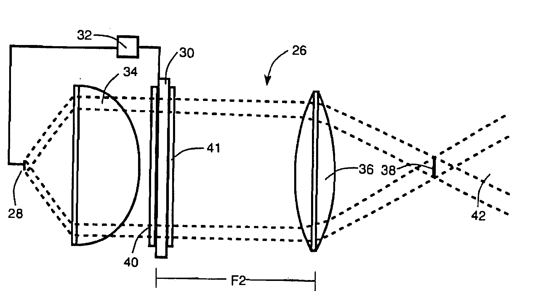
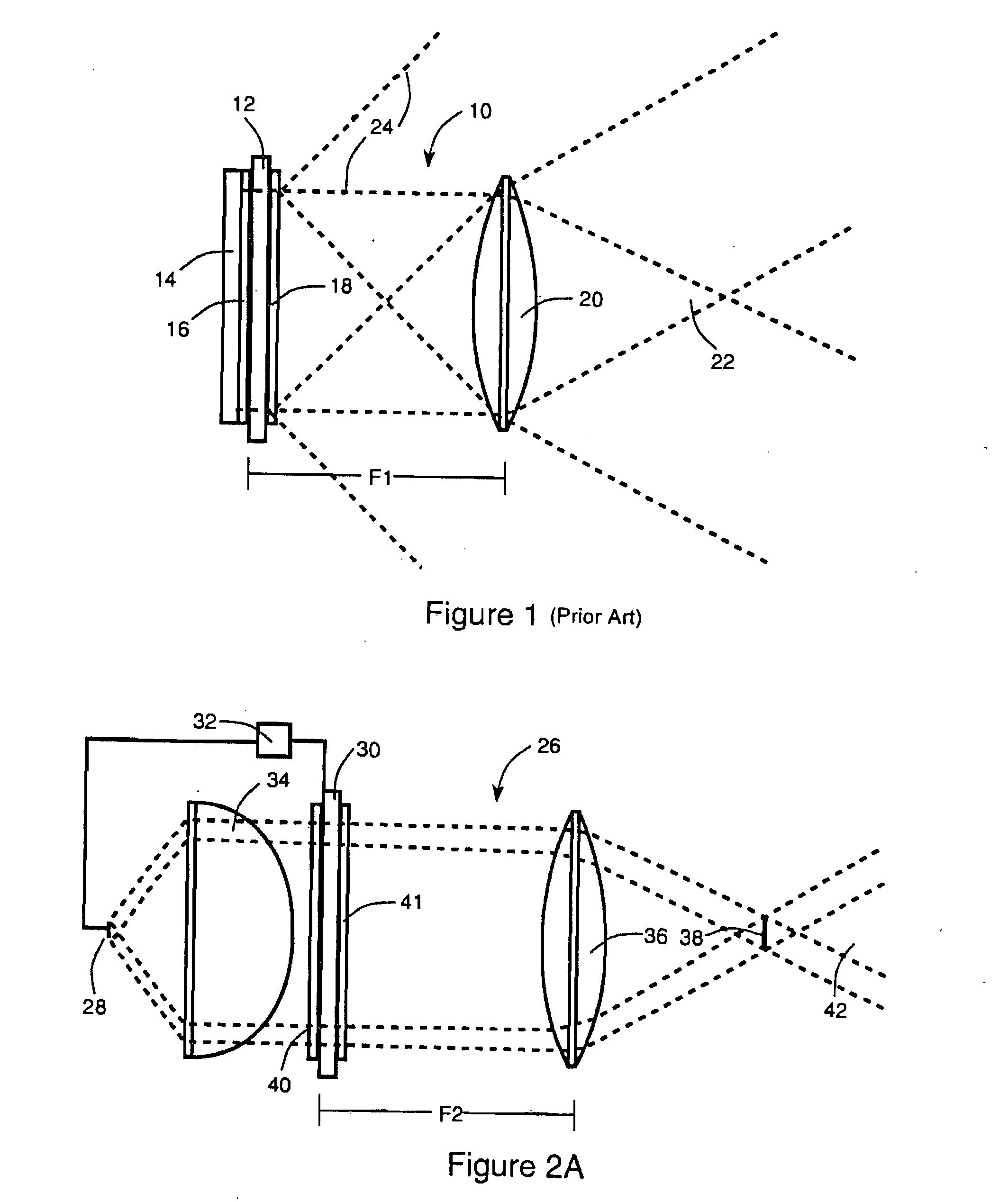
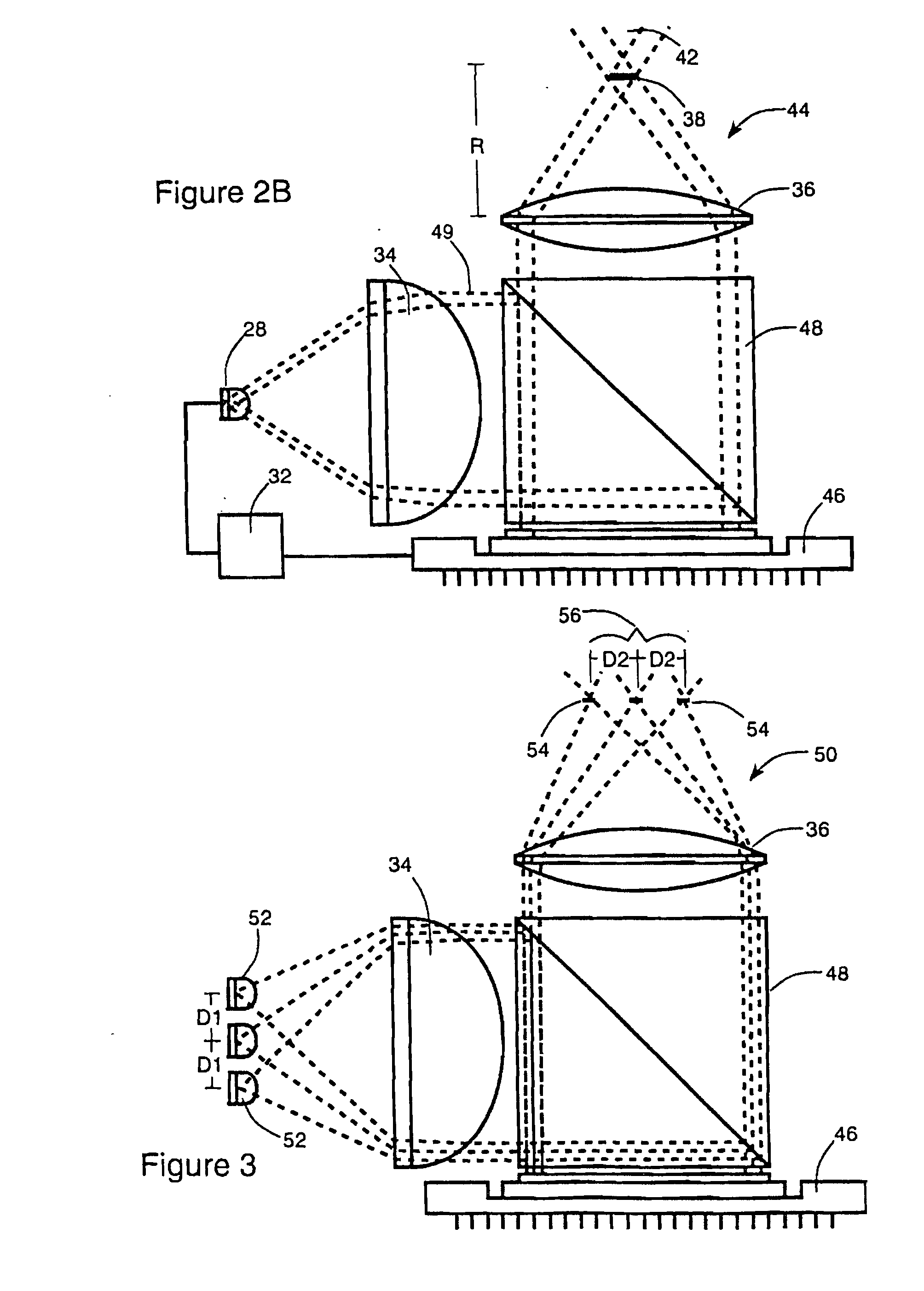
[0034] Turning to FIGS. 2-18, wherein like components are designated by like reference numerals throughout the various Figures, attention is initially directed to FIG. 2A. This Figure illustrates the general optical elements of an optical system, designed in accordance with the present invention, for an image generating system, or miniaturized assembly for producing modulated light, including a spatial light modulator. In this case, the system is a miniature display system generally indicated by reference numeral 26. As shown in FIG. 2A, a suitable and readily providable light source 28 is positioned away from a transmissive spatial light modulator 30 having an writing arrangement 32 for controlling the light modulating states of spatial light modulator 30. Writing arrangement 32 may also switchably control light source 28. Spatial light modulator 30 modulates light from light source 28 by selectively changing the polarization of the light passing through the spatial light modulator...


PUM

PropertyMeasurementUnit
distancesaaaaaaaaaa
diameteraaaaaaaaaa
sizeaaaaaaaaaa

Abstract

A system for producing modulated light is disclosed. The system comprises a spatial light modulator including a light modulating medium switchable between different states so as to act on light in ways which form overall patterns of modulated light. The system also includes an arrangement for switching the modulating medium between the different states in a controlled way and an illumination arrangement for producing a source of light. The system further includes an optics arrangement for directing light from the source of light into the spatial light modulator and for directing light from the spatial light modulator through a predetermined source imaging area. The optics arrangement cooperates with the illumination arrangement and the spatial light modulator so as to produce a real image of the source of light within the source imaging area such that an individual is able to view a virtual image of the overall patterns of modulated light from the source imaging area. A variety of novel optics arrangements are disclosed including specific combinations of different light sources, diffusing plates, polarizers, beam splitters, analyzers, lenses, mirrors, and holographic optical elements which allow the overall optical arrangement to be miniaturized to the same degree and in coordination with the spatial light modulator. The different light sources include using a plurality of light sources, such as LEDs, to form an array of light sources, each of the light sources providing light to a corresponding portion of the spatial light modulator.

Description

GOVERNMENT CONTRACT CLAUSE [0001] This invention was made with Government support under contracts NAS9-18858 and NAS9-19102 awarded by the National Aeronautics and Space Administration and contracts DAA-H01-92-C-R275 and DAA-H01-94-C-R154 awarded by the Advanced Research Projects Agency. The Government has certain rights in this invention.BACKGROUND OF THE INVENTION [0002] The present invention relates generally to image generating systems, and more particularly to optics arrangements and light source arrangements especially suitable for miniaturized image generating systems such as the miniaturized image generator disclosed in U.S. Pat. No. 5,748,164 entitled ACTIVE MATRIX LIQUID CRYSTAL IMAGE GENERATOR, which is incorporated herein by reference. [0003] One of the ongoing challenges facing the manufacture of miniature image generating systems is providing smaller and smaller systems. Miniature image generating systems which are small enough to be mounted onto a helmet or small enou...

Claims


Application Information

Patent Timeline
Patent Type & Authority Applications(United States)
IPC IPC(8): G02B26/00G02B27/14G02F1/13357
CPCG02B6/0033G02B6/0056G02B27/1033G02B27/1053G02B27/1086G02B27/123G02B27/145G02B27/283G02F1/133526G02F1/1336G02F1/133606G02F1/133609G02F1/13362G02F1/136277G02F2001/133616G02F2001/133622Y10S362/80G02F1/133616G02F1/133622
Inventor HANDSCHY, MARK A.MEADOWS, MICHAEL R.CHASE, HOLDEN
Owner DISPLAY TECHNOLOGIES INC
Why Eureka
Try Eureka