
Method for implementing radiation hardened, power efficient, non isolated low output voltage DC/DC converters with non-radiation hardened components

a technology of non-radiation hardening and low output voltage, which is applied in the direction of dc-dc conversion, power conversion systems, instruments, etc., can solve the problems of application failure at relatively low radiation levels, high price and longer delivery times of radiation-tolerant dc/dc converters, and many forms of radiation damage to dc/dc converters. achieve the effect of increasing the radiation dose, increasing the gate voltage signal, and increasing the signal magnitud

Active Publication Date: 2006-05-18
SUMMER STEVEN E
View PDF18 Cites 5 Cited by
  • Summary
  • Abstract
  • Description
  • Claims
  • Application Information

AI Technical Summary

Benefits of technology

[0011] When providing a gate drive signal, the gate drive signal must be sufficiently high in magnitude to saturate the drain to source channel. It must, however, not be so high that the gate to source breakdown voltage rating of the FET is exceeded. It is important to maximize the magnitude of the gate voltage signal, because the higher the signal magnitude is, the higher radiation dose the FET will tolerate and still work acceptably in the circuit.

Problems solved by technology

In these specific applications, the DC / DC converters are subjected to many forms of radiation damage.
However, these parts have limited sources, are expensive and may have long lead times, leading to higher prices and longer delivery times for the radiation tolerant DC / DC converters that incorporate these types of parts.
When conventional non-radiation hardened N Channels FETs are used in applications where radiation is present, the application tends to fail at relatively low radiation levels because the gate threshold voltage of the N channel FET shifts more negatively, and ultimately falls close to zero.
Therefore, the part is uncontrollable.

Method used


Image

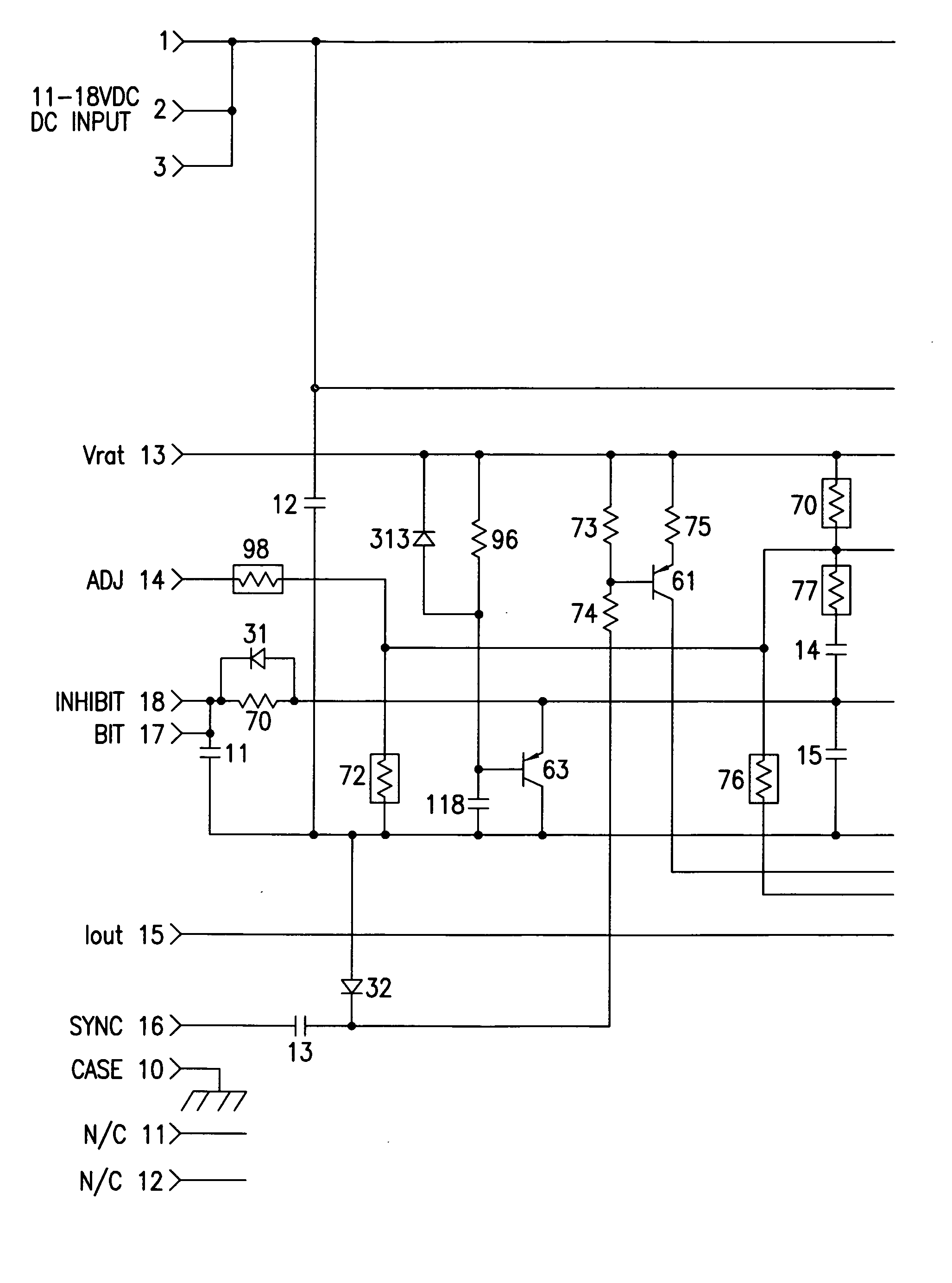
  • Method for implementing radiation hardened, power efficient, non isolated low output voltage DC/DC converters with non-radiation hardened components
  • Method for implementing radiation hardened, power efficient, non isolated low output voltage DC/DC converters with non-radiation hardened components
  • Method for implementing radiation hardened, power efficient, non isolated low output voltage DC/DC converters with non-radiation hardened components

Examples


Embodiment Construction

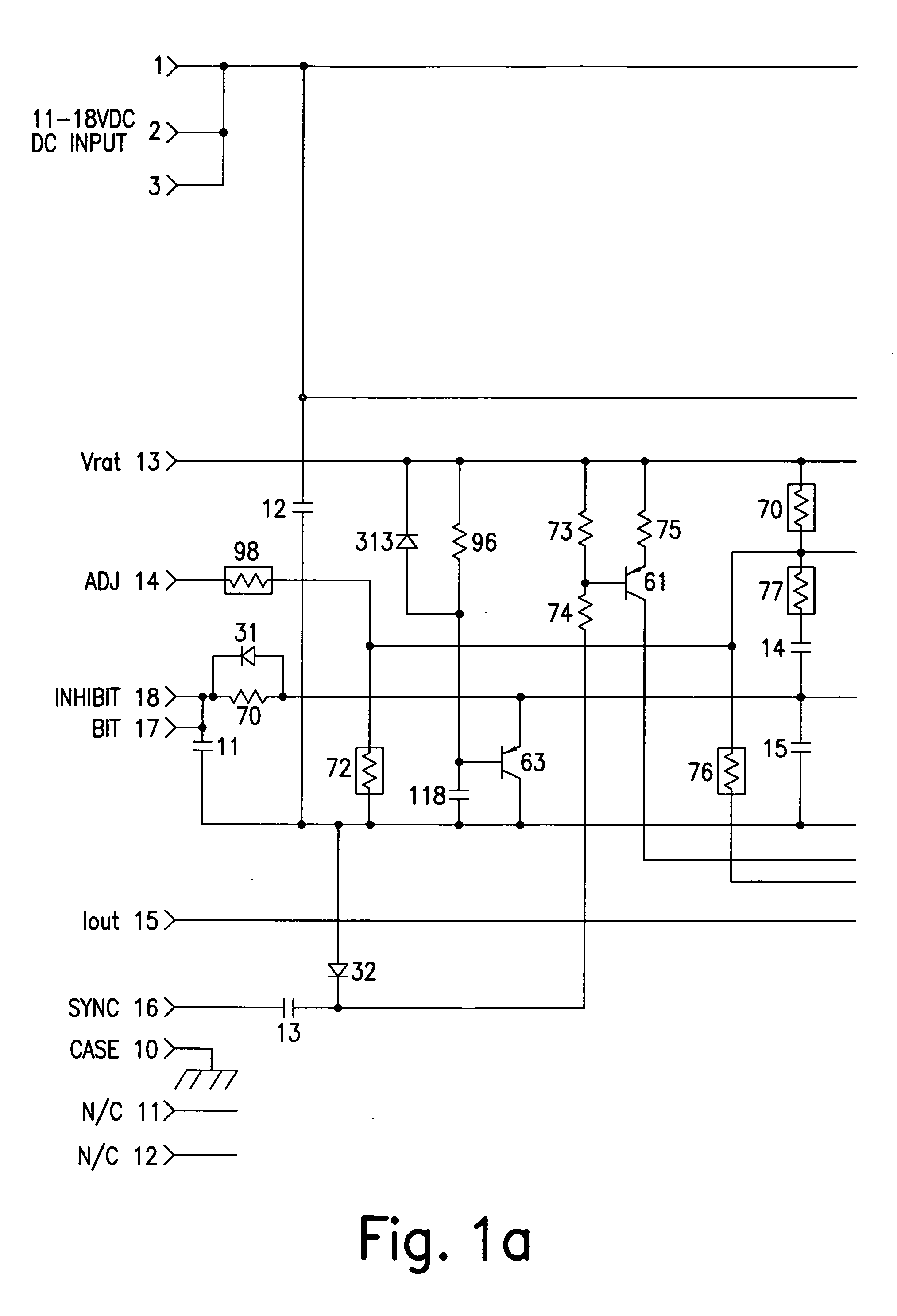
[0017] The following describes the operation of the circuit when connected as a buck converter (step down), wherein terminal B is tied to terminal D, terminal A is tied to terminal C and terminal F is tied to terminal E.

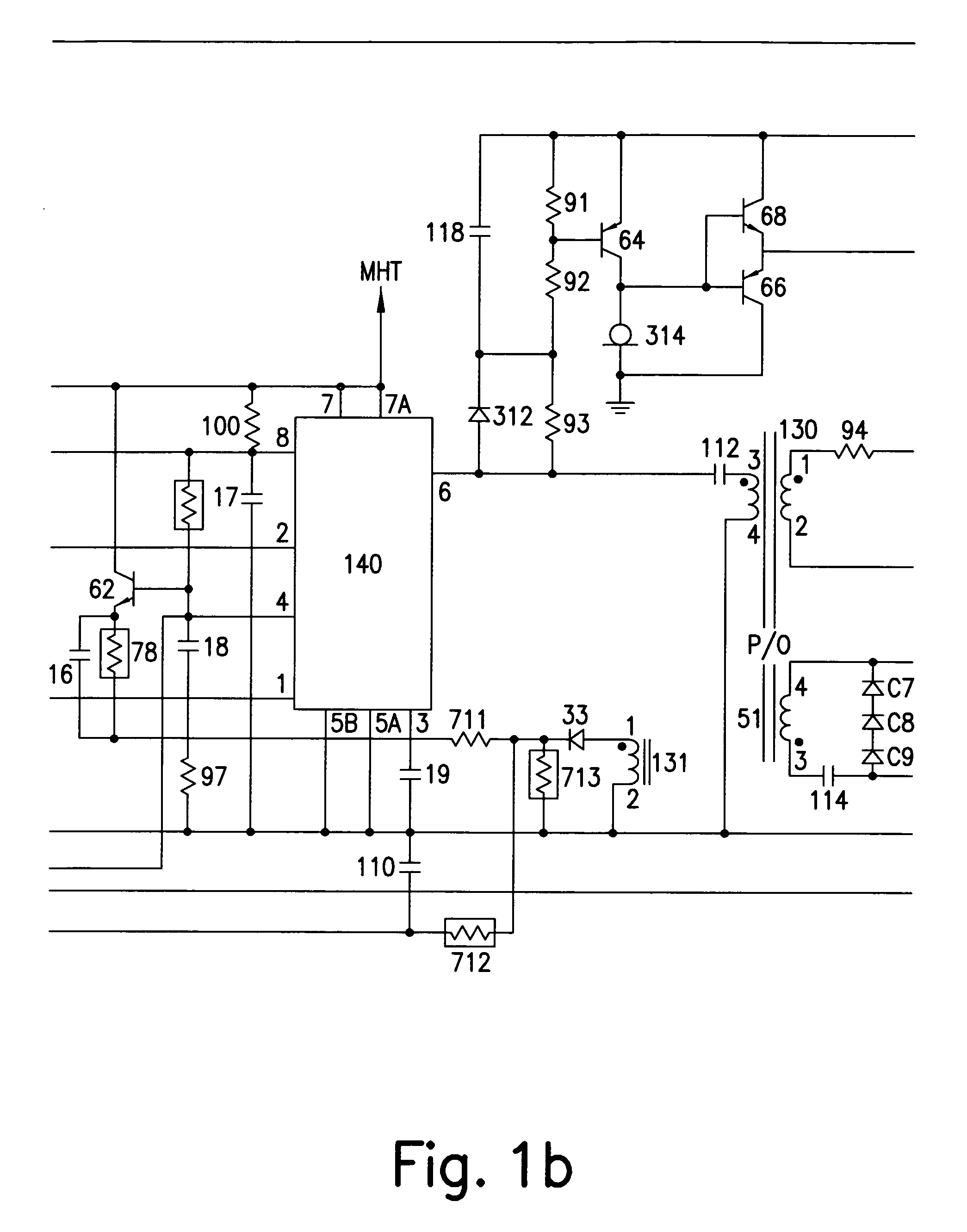
[0018] Positive input voltage is applied through current transformer primary 131 to the source of the P channel FET 65. When 65 conducts at the beginning of the switching cycle, positive input voltage is connected to terminal 1 of inductor 51. Current flows through 51 to the load, and also to filter capacitor 116.

[0019] When PWM circuit 140 switches, and FET 65 is made to turn off, 51 inductor current initially flows through diode 312. Approximately 100 nanoseconds later, P channel FET 67 conducts, connecting terminal 1 of 51 to the common ground. Since the voltage drop across 67 is lower than the forward voltage drop of 312, 51 inductor current flows through FET 67 when 67 conducts.

[0020] Near the end of the switching cycle, approximately 100 nanoseconds before t...


PUM


Abstract

A method of producing an economical DC / DC converter that efficiently produces a relatively low output voltage and operates in a high ionizing radiation dose environment such as found in spacecraft and particle accelerator applications. That is, the converter comprises two P-channel FETs, a switching means for switching conductivity between the two P-channel FETs, and output means for outputting an output voltage. The output voltage being a step-down voltage that is unaffected by high-ionizing radiation such that is found in space or particle accelerators.

Description

FIELD OF THE INVENTION [0001] The object of this invention is a method of producing an economical DC / DC converter that efficiently produces a relatively low output voltage and that operates in a high ionizing radiation dose environment such as found in spacecraft and particle accelerator applications. BACKGROUND OF THE INVENTION [0002] DC / DC converters are electronic devices that use switching devices to transform voltage from one level into another level. Typically, the output voltage is regulated and protected against short circuits. The input and output potentials may be galvanically isolated from each other or, they may have a common galvanic connection, and so be non-isolated from each other. [0003] DC-DC converters whose input is non-isolated from its output tend to be more power efficient (i.e., have less power loss) than isolated DC-DC converters. [0004] Among many applications, these types of devices are used in spacecraft, satellites and in high energy physics instrumentat...

Claims


Application Information

Patent Timeline
Patent Type & Authority Applications(United States)
IPC IPC(8): H02M5/45
CPCH02M3/155H02M3/335
Inventor SUMMER, STEVEN E.
Owner SUMMER STEVEN E
Learn More